
Hybrid filter element and method

a filter element and hybrid technology, applied in the direction of moving filter element filters, filtration separation, separation processes, etc., can solve the problems of affecting process performance, affecting the overall solvent flow, and requiring a large number of carbon filters to accommodate the total solvent flow,

Inactive Publication Date: 2007-11-01
PERRY EQUIPMENT
View PDF5 Cites 28 Cited by
  • Summary
  • Abstract
  • Description
  • Claims
  • Application Information

AI Technical Summary

Benefits of technology

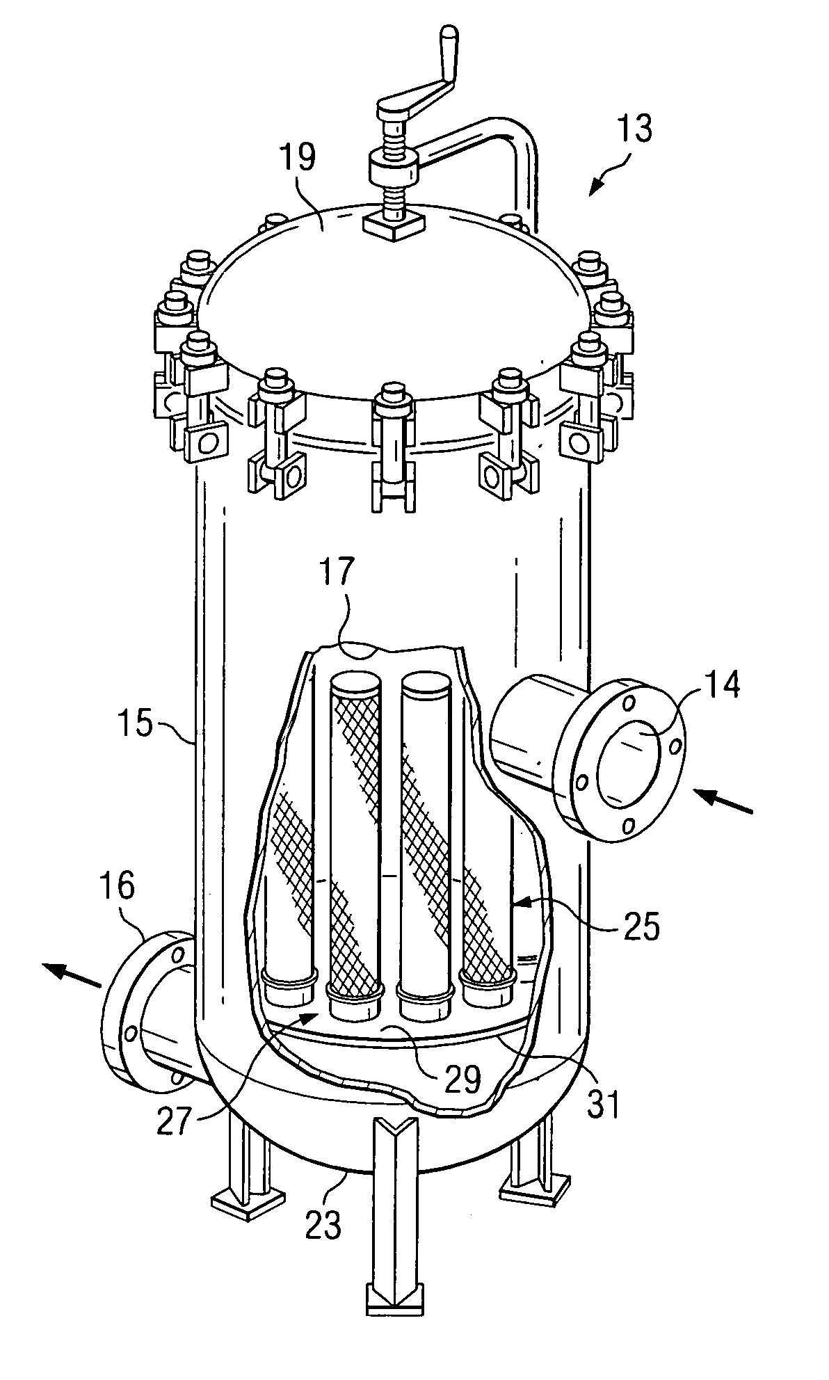
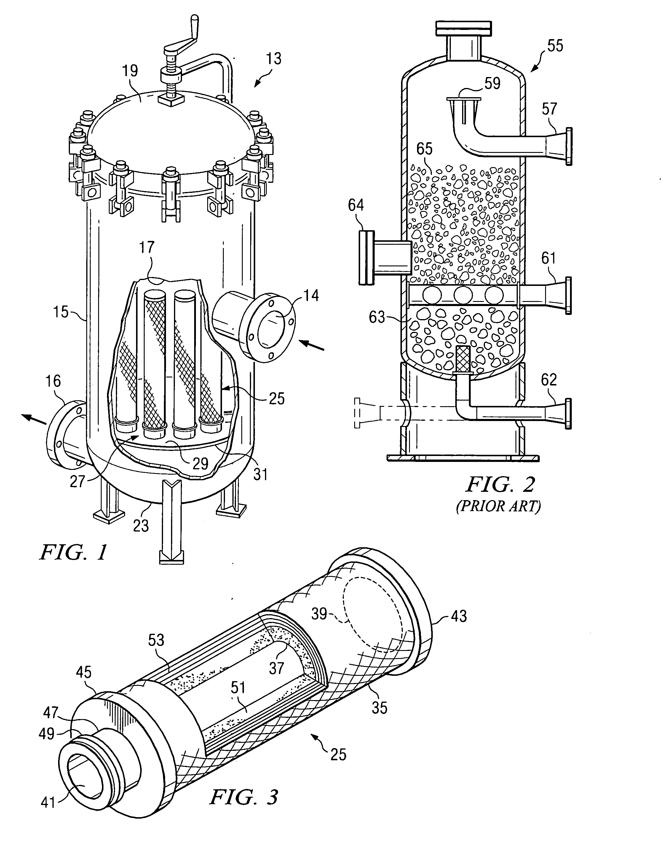
[0012] It is accordingly an object of the present invention to provide a system that eliminates the need for multiple housings in a filtration process of the type described, replacing the multiple housings with a single housing.
[0013] Another object of the invention is to accomplish the elimination of multiple filter housings of the above described type, while also improving the overall filtration effect achieved, and while also providing the capability to filter the full process stream in almost all cases.

Problems solved by technology

However, hydrocarbons and other non-solid contaminants are also present in small quantities and eventually build up, having a detrimental effect on the process performance.
Activated carbon filters of this type work quite effectively, but are subject to certain limitations.
First of all, due to the limited flow rate allowed through the carbon, the carbon filters must be very large to accommodate the total solvent flow.
Using a slip stream reduces the size of the carbon vessel which is required, but treats the solvent less effectively than where a full flow filter is utilized.
Another limitation of the state of the art vessels concerns the fact that the GAC will release carbon fines into the process stream during the filtration operation, which requires that another solids filter be placed downstream of the carbon filter.

Method used


Image

  • Hybrid filter element and method
  • Hybrid filter element and method

Examples


Embodiment Construction

[0028] The particular type of filter vessel utilized with the improved filter elements of the invention may assume various configurations. For example, those familiar with the oil and gas production industries will be familiar with filtration vessels containing filter elements for filtering dry gas streams as well as for separating solids and liquids from contaminated gas streams. Often these types of vessels are installed in a gas pipeline, to perform these filtering functions. U.S. Pat. Nos. 5,919,284, issued Jul. 6, 1999, and 6,168,647, issued Jan. 2, 2001, both to Perry, Jr., and assigned to the assignee of the present invention, disclose filtration vessels using individual filter elements to separate solids, filter liquids, and coalesce liquids. The foregoing multi-stage vessels, as well as a multitude of other similar filtration vessels used in industry utilize solid or hollow core tubular elements, typically formed at least party of a porous filtration media. For example, por...


PUM

PropertyMeasurementUnit
Temperatureaaaaaaaaaa
Thicknessaaaaaaaaaa
Lengthaaaaaaaaaa

Abstract

The present invention relates to an apparatus for filtering a gas or liquid stream of impurities and to filter elements used in such an apparatus. The apparatus includes a closed vessel having a longitudinally extending length, an initially open interior, an input port at one extent and an output port at an opposite extent thereof. A partition located within the vessel interior divides the vessel interior into a first stage and a second stage. At least one opening is provided in the partition. A filter element is disposed within the vessel to extend from within the first stage. The filter element is made up of a carbon block filter media surrounded by a protective porous depth filter media.

Description

BACKGROUND OF THE INVENTION [0001] 1. Field of the Invention [0002] The invention relates to filter elements and filter vessels used to filter gas and liquid streams such as natural gas streams, natural gas processing liquid streams, industrial chemical streams and the like. [0003] 2. Description of The Prior Art [0004] Many separation processes use liquid solvents to physically or chemically adsorb or absorb chemical species from gases or liquids. These solvents remove the specific contaminant from the stream (at which point they are referred to as being “rich”) and are then regenerated with the substance being stripped from the solvent by temperature or by other means. The now “lean” solvent can then be brought into contact with the process stream. This provides for a continuous loop of the solvent being enriched and then stripped of the substance being removed. These solvent processes are used to either purify the process stream by removing a contaminant or to recover and / or con...

Claims


Application Information

Patent Timeline
IPC IPC(8): B01D25/00
CPCB01D39/163B01J2220/66B01D39/2062B01D2239/0208B01D2239/04B01D2239/045B01D2239/0622B01D2239/0627B01D2239/064B01D2239/065B01D2239/0668B01D2239/0695B01D2239/086B01D2239/10B01D2239/1291B01J20/20B01J20/28014B01J20/28023B01J20/2803B01J20/28033B01J20/2804B01J20/28042B01J20/28052B01D39/2013
Inventor KROGUE, JOHN A.CLOUD, DANIEL
Owner PERRY EQUIPMENT
Learn More