
Passive Transmitter Receiver Device Fed by an Electromagnetic Wave

Inactive Publication Date: 2007-11-01
PYGMALYON
View PDF5 Cites 60 Cited by
  • Summary
  • Abstract
  • Description
  • Claims
  • Application Information

AI Technical Summary

Benefits of technology

[0014] The present invention provides for a simple, small solution, which can easily be applied to an object or an individual.
[0017] Advantageously, the loop is intended to be positioned in three planes roughly perpendicular to each other. In this way, the antenna covers the three directions of the space and can therefore capture the electromagnetic waves whatever their orientation.

Problems solved by technology

This solution is expensive and requires a complex computerized management of the different terminals in order to avoid duplicate validations if the object to be detected is in motion.
All the labels of one and the same object do not necessarily capture the electromagnetic wave, so such an updating of the chips is difficult to envisage.
However, it does not allow for the use of a small-size support, smaller than a meter and even more so smaller than 50 cm, that can be easily applied to an object or carried by an individual.
Furthermore, this antenna does not allow for detection in a plane perpendicular to the pallet.

Method used


Image

  • Passive Transmitter Receiver Device Fed by an Electromagnetic Wave
  • Passive Transmitter Receiver Device Fed by an Electromagnetic Wave
  • Passive Transmitter Receiver Device Fed by an Electromagnetic Wave

Examples


first embodiment

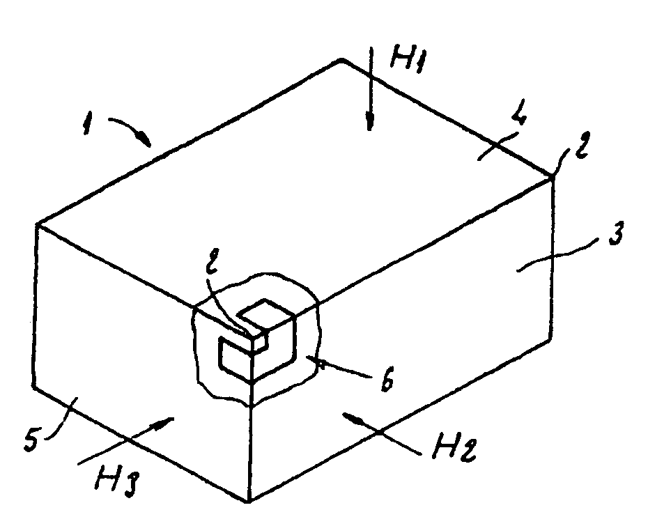
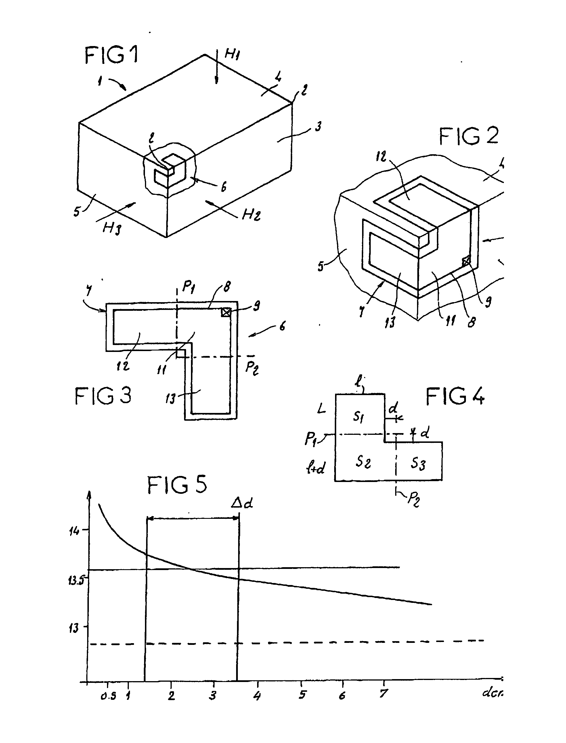
[0039] A parallelepipedal package 1, as represented in FIG. 1, has eight corners 2, each corner 2 being delimited by three sides 3, 4, 5 perpendicular to each other. A device 6 according to the invention is glued to one corner 2 so as to be in contact with the three sides 3, 4, 5, as represented in FIG. 2.

[0040] To do this, the device 6 takes the form of a flat label, represented in FIG. 3, comprising an adhesive support 7 in the shape of a bracket made of a foldable flexible material such as paper or polymer film. A conductive wire 8, having two ends, is deposited around the edge of the support 7 so as to form a loop also in the shape of a bracket. The conductive wire 8 can be joined to the support 7 or not. Alternatively, the loop can also be produced in the form of a conductive track obtained by metallic deposition or from a conductive ink.

[0041] The ends of the wire 8 are linked to the power supply terminals of an electronic transponder chip 9. Such an electronic chip 9 is know...

second embodiment

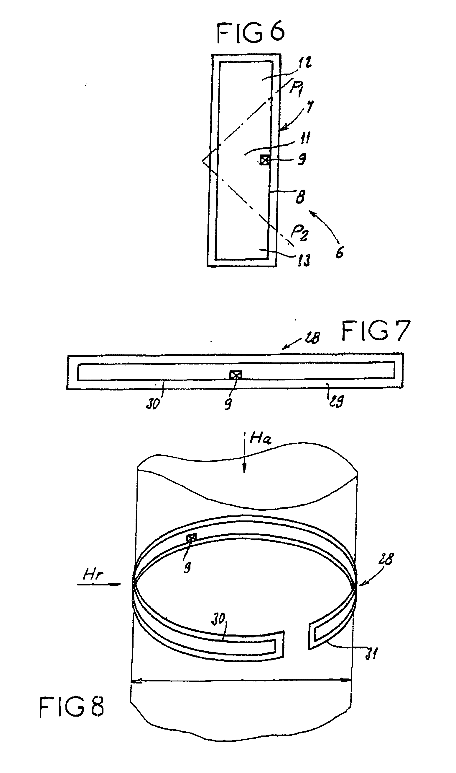
[0067] A device 28, according to the invention and as represented in FIGS. 7 and 8, comprises a flat support 29 in the form of a flexible strip. A wire 30 is placed around the edge of the support 29 to form a rectangular loop and is connected to an electronic chip 9. The support 29 is covered by a protective film, then the device is glued onto an open bracelet 31 having dimensions close to those of the support 29. In conditions of use, the open bracelet 31 is placed around a roughly cylindrical body, such as a wrist or an ankle so as to form a bracelet. The loop formed by the wire 30 then has an open bracelet structure and therefore presents receiving surface areas with which to capture the radially oriented waves Hr and the waves Ha oriented along the axis of the cylinder.

[0068] The fact that the bracelet 31 is an open bracelet means that the device 28 can easily be adapted to different diameters. The surprising particular feature of a loop with an open bracelet structure is that t...

third embodiment

[0070] Moreover, the elasticity of the spiral means that the device 33 can easily be adapted to different diameters without any specific opening device. As for the device 28, it has been observed that the resonance frequency varies little with the diameter. The curve of the resonance frequency as a function of the diameter of the loop is represented in FIG. 12.

[0071]FIG. 13 represents a device 35 according to a fourth embodiment, intended to be glued onto the corner of a package, as in the first embodiment, comprising a wire describing on each side of the packet two perpendicular sections, so as to form a left hexagon around one corner of the packet, the chip 37 being situated, for example, on a vertex of the hexagon.

[0072]FIG. 14 represents a device 38 according to a fifth embodiment intended to be glued onto the corner of a package, as in the first embodiment, which is similar to the first embodiment except that its shape is not in the form of an L with straight line segments, b...


PUM


Abstract

The invention relates to a passive transmitter-receiver device (6,28,33) fed by an electromagnetic wave, provided with an antenna comprising a loop (7, 30, 34) which is associated with an electronic transponder chip (9), said loop being able to feed the electronic chip by an induced current which is generated when it is cross-flown by an electromagnetic wave (H1, H2, H3, Ha, Hr) carrying information, and to transmit a second electromagnetic wave carrying a response from the electronic chip. The antenna is configured in such a way that the loop includes at least two non-coplanar or non-parallel parts in a position of use.

Description

BACKGROUND OF THE INVENTION [0001] The present invention relates to a passive receiver-transmitter device powered by an electromagnetic wave carrying information. [0002] The operation of such devices relies on a transmission by induction between, on the one hand, a card or a label having an antenna in the form of a loop, the ends of which are linked to an electronic chip on the card or the label, and, on the other hand, a terminal capable of sending and receiving an electromagnetic wave carrying information. The antenna of the card or label captures the electromagnetic wave sent by the terminal and transmits the information to the chip which processes it before, if necessary, sending a response that is forwarded by the antenna and will be captured by the terminal. Thus, the latter can read and / or modify the information stored on the card. [0003] Such devices are used to implement so-called “contactless” data transfer methods, used, for example, for remote identification systems, for...

Claims


Application Information

Patent Timeline
IPC IPC(8): H01Q1/24G01S13/02G06K19/077H01Q1/22H01Q1/38H01Q7/00
CPCG06K19/07749G06K19/07758H01Q7/00H01Q1/2225H01Q1/38H01Q1/22G06K19/077H04B1/59G01S13/02
Inventor MARTIN, JEAN-MARC
Owner PYGMALYON
Learn More