Method and apparatus for power converters having phases spaced at desired phase angles

a power converter and phase angle technology, applied in the field of multiple power converters, can solve the problems of difficult synchronization, difficult synchronization, and difficulty in obtaining high efficiency in switching power supplies, and achieve the effect of reducing switching losses

Active Publication Date: 2007-11-01
TEXAS INSTR INC
View PDF16 Cites 33 Cited by
  • Summary
  • Abstract
  • Description
  • Claims
  • Application Information

AI Technical Summary

Benefits of technology

[0010]Briefly stated, the present disclosure provides a system and method for power conversion that synchronizes multiple phases at a desired phase angle difference. The power conversion involves variable frequency switching, fixed on-time and provides power factor correction. A relative measure of a phase angle difference between two phases permits each phase to be controlled to obtain the desired phase angle difference. The power conversion involves transition mode switching to help reduce switching losses. A phase angle difference detector may be provided for each phase. The various phases may have different inherent frequencies that vary with switching frequency, and are synchronized to an average frequency.
[0013]Two or more waveform generators may be used to generate the periodic waveforms. Each waveform generator is responsive to a separate indication of a relative phase angle difference between periodic waveforms of different phases. The relative phase angle difference is a differential measure between cycles of periodic waveforms of different phases, as measured from one phase to the other, using either phase as the starting point. The relative phase angle difference can thus be a measure from a first phase to another, a measure from another phase to the first, or both. The use of both relative measures provides additional control freedoms to help speed the relative synchronization of the phases at a desired phase angle difference. The phase angle difference may be determined, for example, by measuring a time interval between cycle start points of the periodic waveforms of two different phases.

Problems solved by technology

Due to the variable frequency nature of the power supply switching, it can be challenging to synchronize the various phases to obtain one or more of the above-described advantages.
Obtaining high efficiency in switching power supplies is also challenging, and can be improved with multiple interleaved phases when properly synchronized.
However, the variable frequency nature of the switching power supply makes synchronization of the various power phases somewhat challenging as frequency changes to deliver desired output power characteristics.
One drawback to this approach is the challenge of acquiring and maintaining a phase lock over a wide range of conditions.
The PLL capture range must encompass the difference between the free-running frequencies of the master and slave(s), which may prove difficult or costly in practice.

Method used


Image

  • Method and apparatus for power converters having phases spaced at desired phase angles
  • Method and apparatus for power converters having phases spaced at desired phase angles
  • Method and apparatus for power converters having phases spaced at desired phase angles

Examples


Embodiment Construction

[0034]This application claims the benefit of U.S. Provisional Application No. 60 / 796,420, filed May 1, 2006, the entire content of which is hereby incorporated herein by reference.

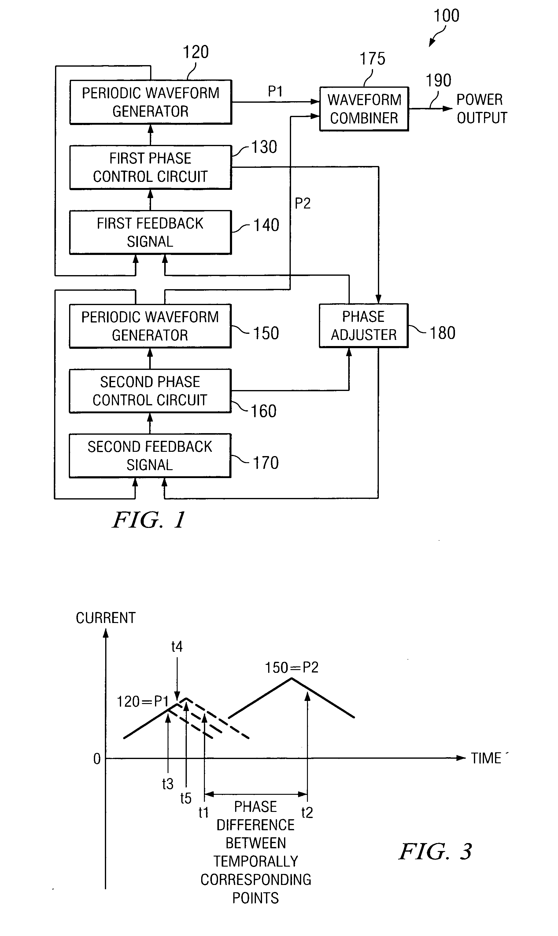
[0035]FIG. 1 is a block diagram of a power converter 100 according to an embodiment of the present invention. For a first phase P1, a periodic waveform generator 120 is coupled to a first phase control circuit 130. A first feedback signal 140 is coupled to the first phase control circuit 130. The first feedback signal 140 influences a shape of the periodic waveform provided by generator 120. Similarly, for a second phase P2, a periodic waveform generator 150 is coupled to a second phase control circuit 160. A second feedback signal 170 is coupled to the second phase control circuit 160. The second feedback signal 170 influences a shape of the periodic waveform provided by generator 150.

[0036]A phase adjuster 180 is connected to the first phase control circuit 130 and the second phase control circuit 160. T...


PUM


Abstract

A system and method for power conversion synchronizes multiple phases at a desired phase angle difference. The power conversion involves variable frequency switching, fixed on-time and provides power factor correction. A relative measure of a phase angle difference between two phases permits each phase to be controlled to obtain the desired phase angle difference. The power conversion involves transition mode switching to help reduce switching losses. A phase angle difference detector may be provided for each phase. The various phases may have different inherent frequencies that vary with switching frequency, and are synchronized to an average frequency.

Description

CROSS REFERENCE TO RELATED APPLICATIONS[0001]This application claims benefit of U.S. Provisional Application No. 60 / 796,420, filed May 1, 2006. This application is related to U.S. application Ser. No. (TI-61712) filed May 1, 2007, U.S. application Ser. No. (TI-63508) filed May 1, 2007, and U.S. application Ser. No. (TI-63804) filed May 1, 2007 .STATEMENT REGARDING FEDERALLY SPONSORED RESEARCH OR DEVELOPMENT[0002]Not ApplicableBACKGROUND OF THE INVENTION[0003]1. Technical Field of the Invention[0004]The present invention relates generally to multiple power converters used in conjunction, and relates more particularly to power converters used in conjunction with interleaved phases.[0005]2. Description of Related Art[0006]Performance improvements in interleaved, multiphase power supplies result from advantages such as reduced input current ripple, reduced peak output current and higher frequency output ripple current, the output ripple being thus easier to filter. A particular type of ...

Claims


Application Information

Patent Timeline
Patent Type & Authority Applications(United States)
IPC IPC(8): H02M11/00
CPCH02M1/4216Y02B70/126H02M1/4225Y02B70/10
Inventor COHEN, ISAACNEIDORFF, ROBERT A.VALLEY, RICHARD L.
Owner TEXAS INSTR INC
Why Eureka
Try Eureka