Two-stage rotodynamic blood pump

a rotodynamic and blood pump technology, applied in the field of pumps, can solve problems such as affecting the relative performance of the inlet pressure balancer, and achieve the effect of altering the hydraulic performance of the pump

Active Publication Date: 2007-11-01
THE CLEVELAND CLINIC FOUND
View PDF29 Cites 90 Cited by
  • Summary
  • Abstract
  • Description
  • Claims
  • Application Information

AI Technical Summary

Benefits of technology

[0009]The present invention further relates to a pump including a housing including a pumping chamber and a rotor supported in the housing and rotatable about an axis. The rotor includes an impeller at least partially disposed in the pumping chamber. The rotor is mova

Problems solved by technology

This rotating assembly is free to move axially in response to the hydraulic environment, thereby changing clearan

Method used


Image

  • Two-stage rotodynamic blood pump
  • Two-stage rotodynamic blood pump
  • Two-stage rotodynamic blood pump

Examples


first embodiment

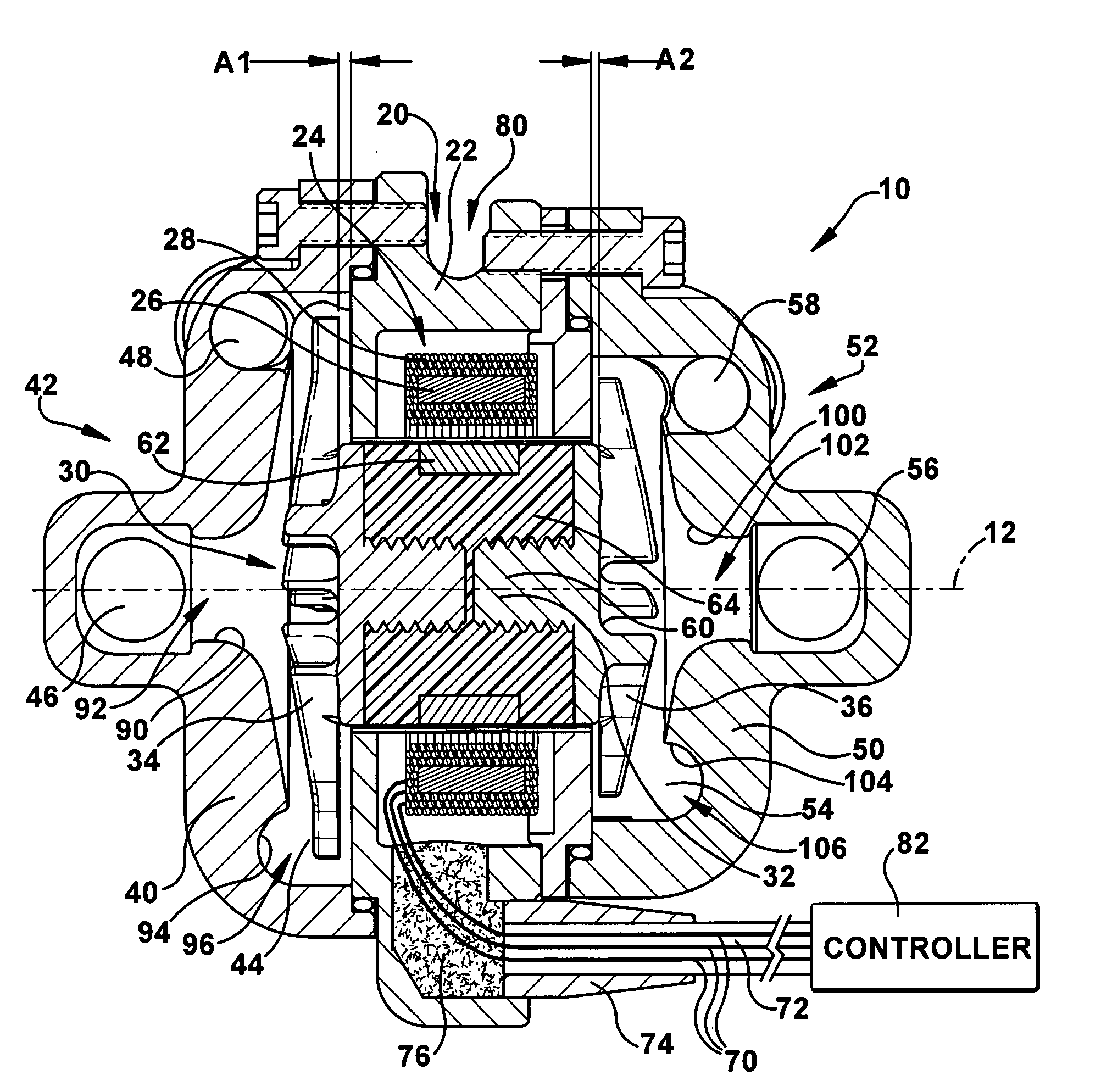
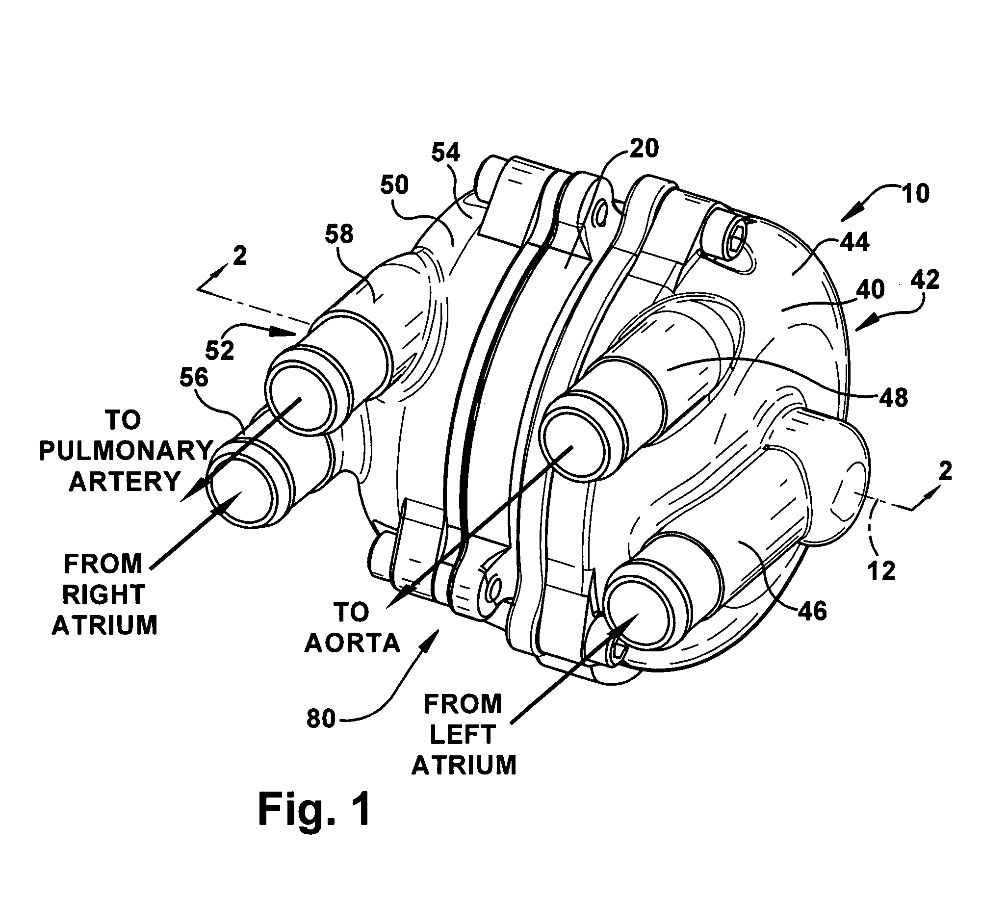
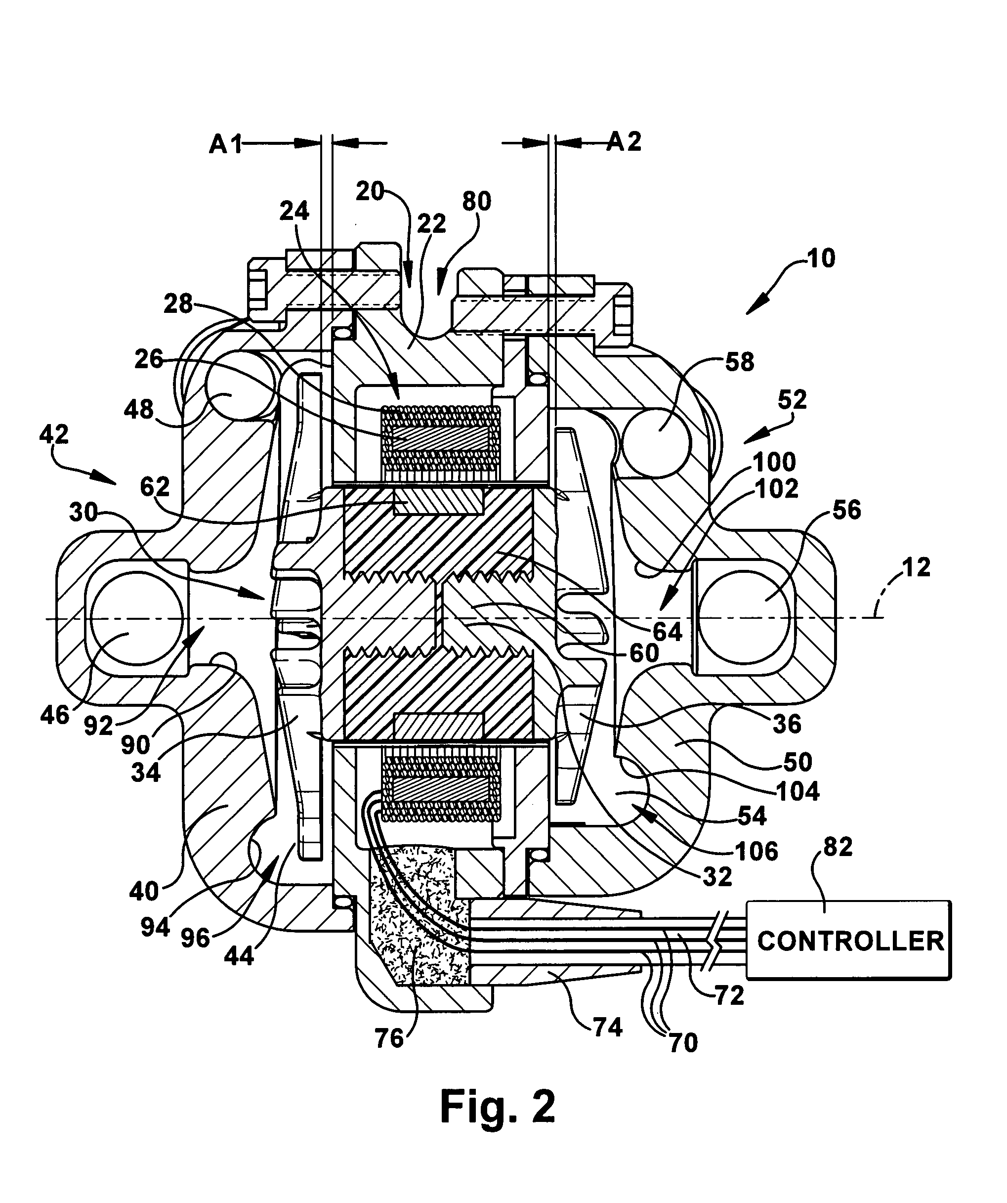
[0023]The present invention relates to a blood pump. FIG. 1 illustrates a blood pump 10 according to the present invention. According to the present invention, the blood pump 10 is a total artificial heart (TAH) device capable of replacing a failing or damaged human heart. Those skilled in the art, however, will appreciate that the blood pump 10 could be suitable for non-TAH implementations, such as biventricular support. Those skilled in the art will also appreciate that the pump may be suited for purposes other than pumping blood, such as any implementation in which a dual or two stage fluid handling pump with pressure balancing features is desired. In the illustrated embodiments, the blood pump 10 is a two-stage centrifugal pump, which is described below in further detail. The blood pump 10 could, however, be a rotodynamic pump of any desired configuration.

[0024]Referring to FIGS. 1-3, the blood pump 10 includes a stator assembly 20, a rotor assembly 30, a left pump housing 40, a...

second embodiment

[0063]Based on this principle, using the blood pump 200, systemic and pulmonary pressure and flow characteristics can be controlled through adjusting the axial position of the rotor assembly 230. According to the present invention, the blood pump 200 is configured for active control of the axial position of the of the rotor assembly 230 and, thus, the geometry or configuration of the left and right pumps 242 and 252.

[0064]It has been found that, for constant system resistances, output flow and pump speed have a linear relationship. It has also been found that, for a given pump speed, there is an electrical power level, obtained by adjusting the axial position of the rotor assembly 230, that corresponds with balanced flows at the left pump 242 and right pump 252. As a result, the control algorithm executed by the controller 282 adjusts pump speed to provide a nominal systemic flow, while balanced systemic and pulmonary flows are achieved by adjusting of the axial position of the roto...

third embodiment

[0073]A blood pump 400 according to the present invention is illustrated in FIG. 7. The blood pump 400 of FIG. 7 has a configuration that is similar to the embodiment of FIG. 6, except that the embodiment of FIG. 7 includes a rotor assembly 410 that does not move axially to alter the pump geometry during operation. In this configuration, the rotor magnet 420 is the same length or longer than the stator core 422, which magnetically constrains the axial position of the rotor assembly 410.

[0074]The blood pump 400 of FIG. 7 may be particularly well-suited for use as a ventricular assist device (VAD), such as a bi-ventricular assist device (BiVAD) that combines right ventricular assist device (RVAD) and left ventricular assist device (LVAD) functions in a single pump. With an RVAD, the total pulmonary artery flow is shared between the VAD and native ventricle, so precise right / left pump control is not as critical as for a total artificial heart. It has been found that performance charact...


PUM


Abstract

A pump (10) includes a housing, a stator (20) supported in the housing, and a rotor assembly (30). The rotor assembly (30) includes a rotor (32) supported in the housing for rotation relative to the stator (20) about an axis (12). The rotor assembly (30) also includes a first impeller (34) operatively coupled to a first axial end of the rotor (32) for rotation with the rotor about the axis (12). The rotor assembly further includes a second impeller (36) operatively coupled to a second axial end of the rotor (32), opposite the first axial end, for rotation with the rotor about the axis (12). The rotor assembly (30) is movable along the axis (12) relative to the housing to adjust hydraulic performance characteristics of the pump (10).

Description

RELATED APPLICATION[0001]This application claims priority from U.S. provisional patent application Ser. No. 60 / 795,096, filed on Apr. 26, 2006, the subject matter of which is incorporated herein by reference.TECHNICAL FIELD[0002]The present invention relates to a pump that may be used in fluid handling applications where two fluid streams are to be balanced. More particularly, the present invention relates to a two-stage rotodynamic pump configuration for providing pulsatile, continuous flow, blood pumping performance.BACKGROUND OF THE INVENTION[0003]Congestive heart failure (CHF) is an increasingly common cause of cardiovascular disability and premature death. Despite advances in medical therapy, heart transplant is the primary course of action for treating patients with end-stage congestive heart failure. Because the availability of donor organs is limited, however, CHF patients may be forced to wait until a suitable donor organ is located. Blood pumping devices, referred to as ve...

Claims


Application Information

Patent Timeline
IPC IPC(8): F04B17/00A61M60/183A61M60/196A61M60/232A61M60/405A61M60/414A61M60/422A61M60/562A61M60/806A61M60/814A61M60/818A61M60/82A61M60/822
CPCA61M1/101A61M1/12F04D1/06A61M1/1017F04D13/064F04D29/042A61M1/1015F04D13/0633A61M2205/3334A61M60/818A61M60/824A61M60/82A61M60/422A61M60/148A61M60/232A61M60/806A61M60/405A61M60/814A61M60/414A61M60/183A61M60/196A61M60/822
Inventor HORVATH, DAVIDGOLDING, LEONARD A.R.MASSIELLO, ALEX
Owner THE CLEVELAND CLINIC FOUND
Why Eureka
Try Eureka