Hydrogen peroxide vaporizer

Active Publication Date: 2007-11-01
AMERICAN STERILIZER CO
View PDF19 Cites 64 Cited by
  • Summary
  • Abstract
  • Description
  • Claims
  • Application Information

AI Technical Summary

Benefits of technology

[0058]An advantage of the present invention is a high-capacity vaporized hydrogen peroxide (VHP) generator.
[0059]Another advantage of the present invention is a decontamination system capable of producing large quantities of vaporized hydrogen peroxide.
[0060]Another advantage of the present invention is a decontamination system as described above having several methods for confirming the flow of vaporized hydrogen peroxide through the system.
[0061]Another advantage of the presen

Problems solved by technology

A problem with the aforementioned drip method of vaporization is that a hot surface must be maintained to vaporize the liquid hydrogen peroxide and water mixture.
At higher injection rates, individual droplets can no longer be maintained.
In other words, the drip-type vaporizer is limited in the amount of vaporized hydrogen peroxide it can produce within given size limits.
This lim

Method used


Image

  • Hydrogen peroxide vaporizer
  • Hydrogen peroxide vaporizer
  • Hydrogen peroxide vaporizer

Examples


Embodiment Construction

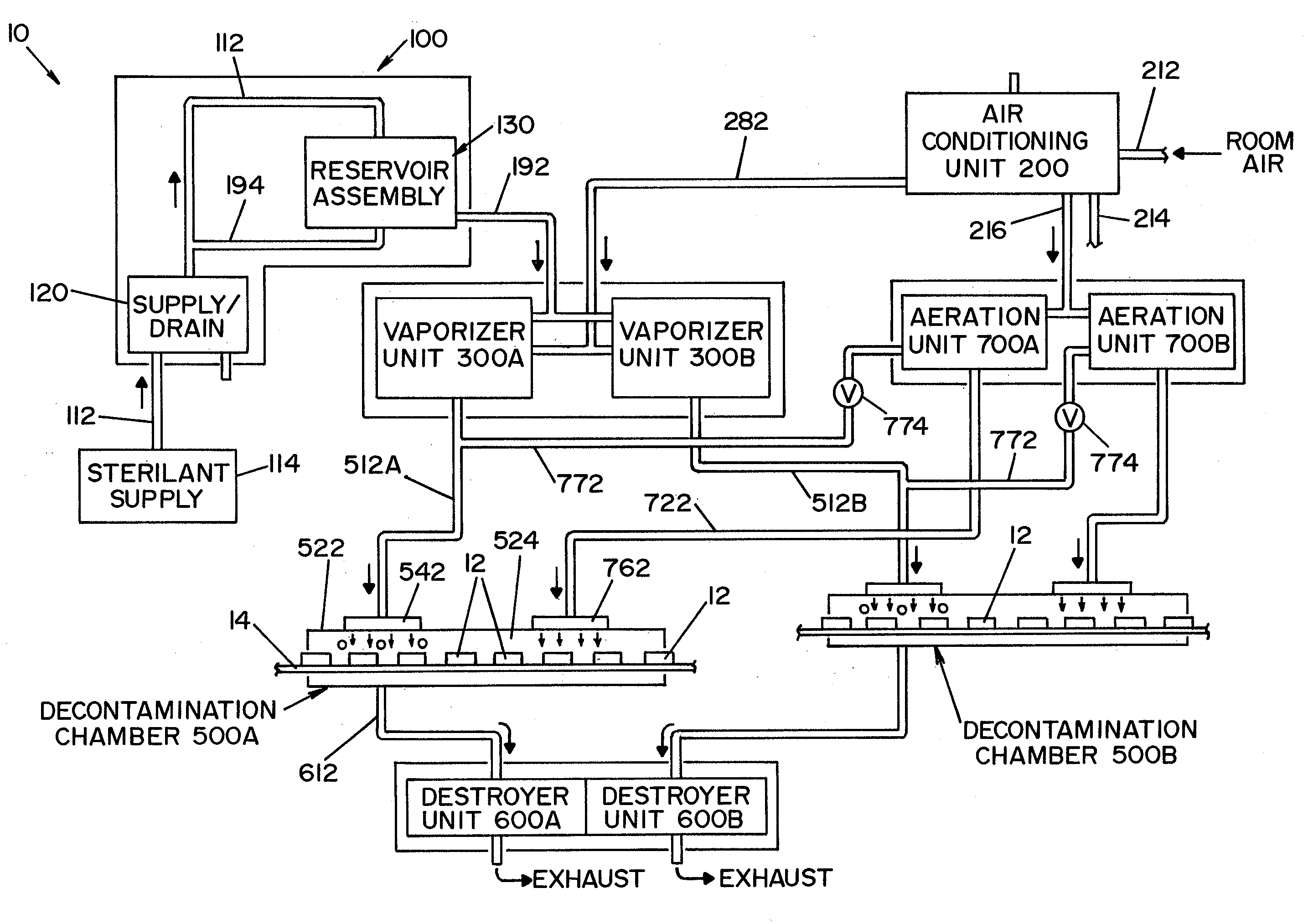
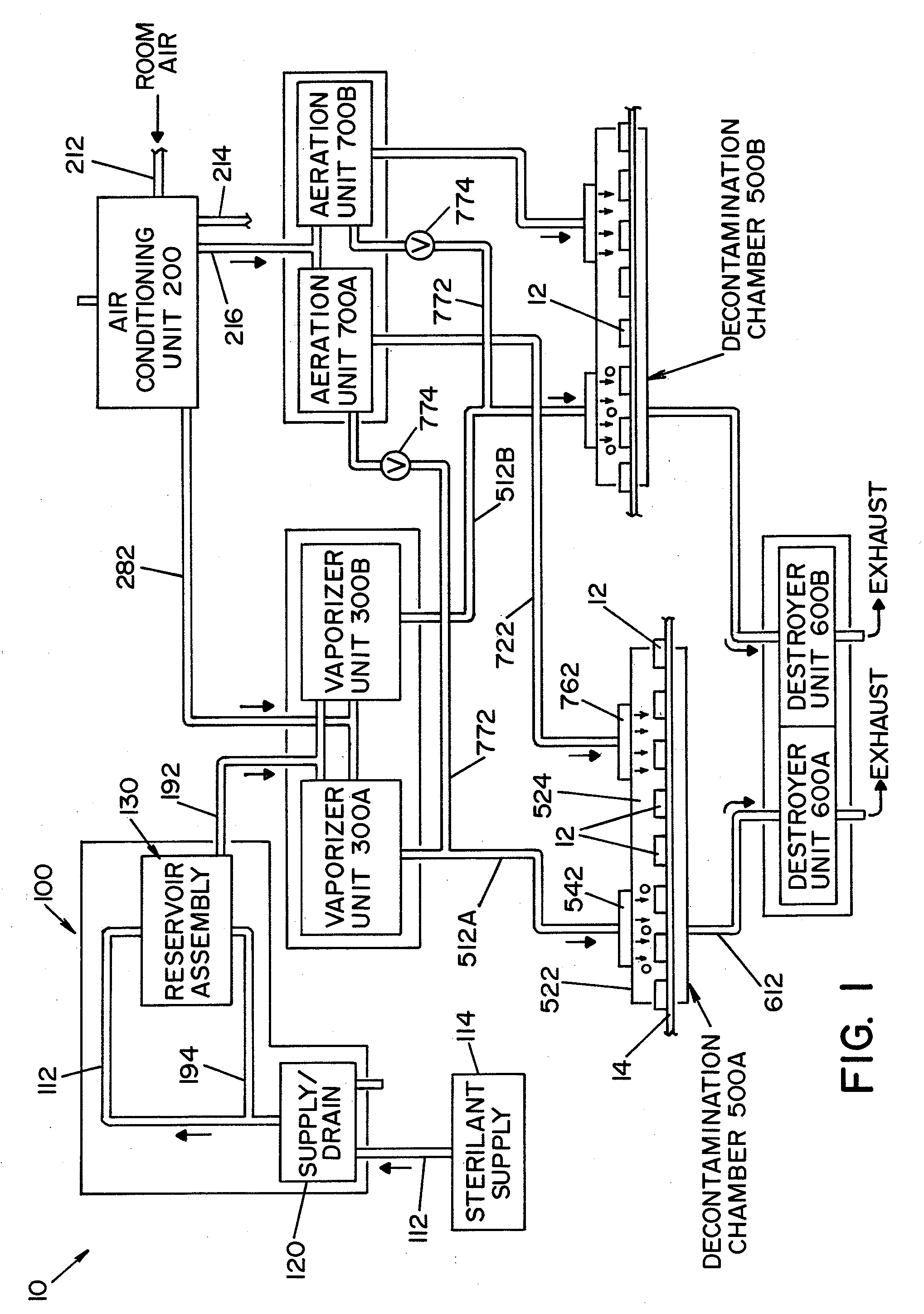
[0085]Referring now to the drawings wherein the showings are for the purpose of illustrating a preferred embodiment of the invention only, and not for the purpose of limiting same, FIG. 1 shows a vaporized hydrogen peroxide decontamination system 10 for continuously decontaminating articles 12 moving along a conveyor belt 14, illustrating a preferred embodiment of the present invention.

[0086]Broadly stated, a decontamination system 10, according to the present invention, is comprised of a sterilant supply unit, an air conditioning unit, a vaporizer unit, a decontamination room or isolator, a destroyer unit and an aeration unit. In the embodiment shown, decontamination system 10 includes a single sterilant supply unit 100, a single air conditioning unit 200, two vaporizer units 300A, 300B, two decontamination rooms 500A, 500B, two destroyer units 600A, 600B and two aeration units 700A, 700B.

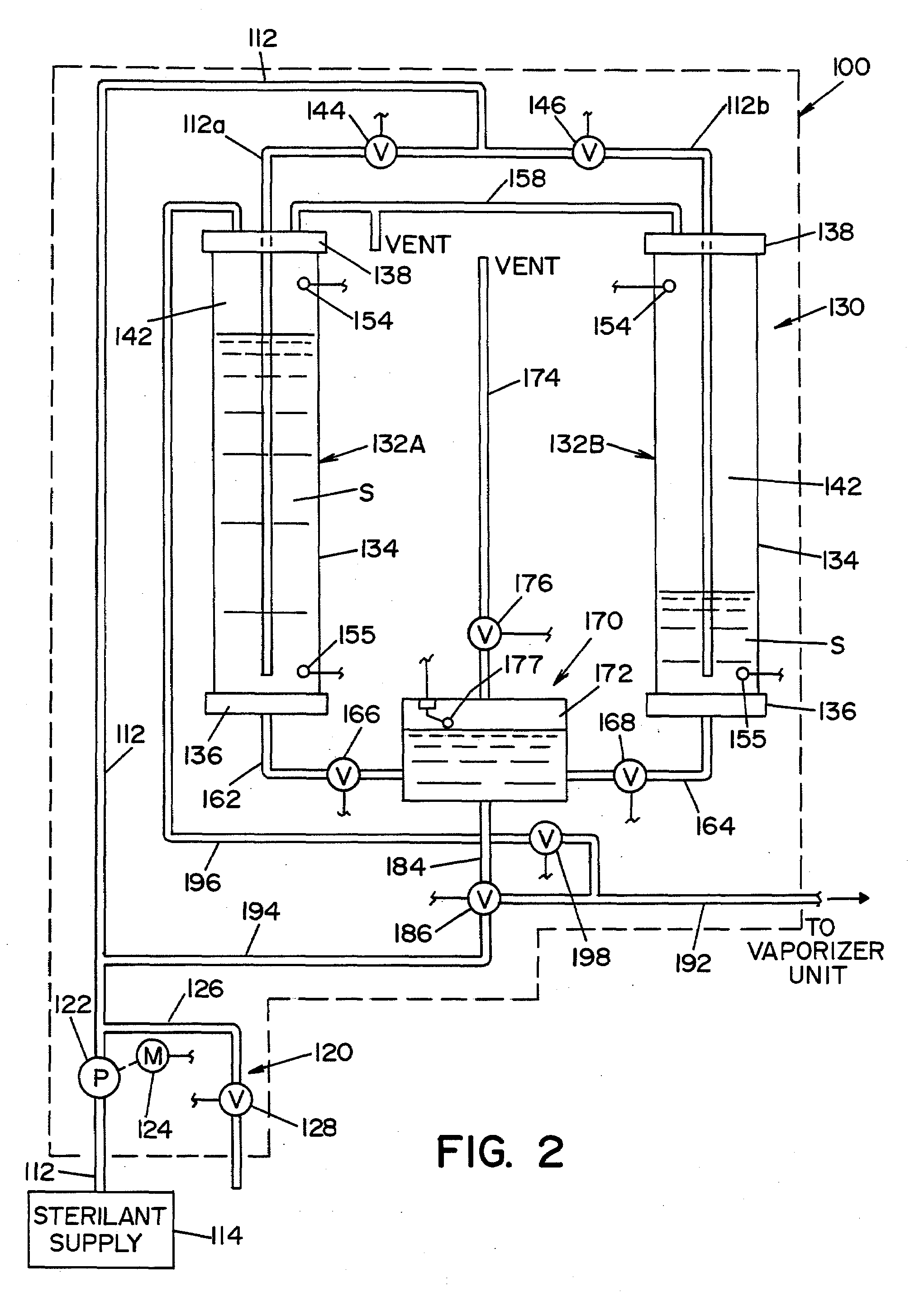
Sterilant Supply Unit 100

[0087]Referring now to FIG. 2, sterilant supply unit 100 is best seen...


PUM


Abstract

A method of decontaminating articles, comprising the steps of:
    • (a) moving a plurality of articles having a known temperature along a first path;
    • (b) conveying a carrier gas along a second path that includes an elongated plenum, the second path intersecting the first path downstream from the plenum;
    • (c) heating the carrier gas to a temperature of at least about 105° C. at a location upstream of the plenum;
    • (d) introducing into the carrier gas in the plenum an atomized mist of a liquid hydrogen peroxide of known concentration; and
    • (e) controlling the following:
      • (1) the volumetric flow of carrier gas along the second path;
      • (2) the volume of hydrogen peroxide introduced into the carrier gas; and
      • (3) the temperature of the carrier gas introduced into the plenum, such that the concentration of the vaporized hydrogen peroxide in the carrier gas where the first path intersects the second path has a dew point temperature below the known temperature of the articles.

Description

FIELD OF THE INVENTION [0001]The present invention relates to the generation of vaporized hydrogen peroxide, and more particularly, to a system for generating large amounts of vaporized hydrogen peroxide and a method of operating the same.BACKGROUND OF THE INVENTION [0002]It is known to use hydrogen peroxide (H2O2) in sterilization and other processes. In a sterilization process, liquid hydrogen peroxide is vaporized to form vaporized hydrogen peroxide (VHP). The vaporized hydrogen peroxide is typically produced from a liquid mixture of hydrogen peroxide and water. Care must be taken when vaporizing this mixture due to the difference in the boiling points between water and hydrogen peroxide. In this respect, water boils at 100° C., whereas pure hydrogen peroxide boils at 150° C. Accordingly, when a mixture of water and hydrogen peroxide is vaporized, the water tends to boil before the hydrogen peroxide unless the mixture is flash vaporized. In conventional systems, flash vaporizatio...

Claims


Application Information

Patent Timeline
IPC IPC(8): A61L2/20
CPCA61L9/22A61L2/208
Inventor HILL, AARON L.
Owner AMERICAN STERILIZER CO
Why Eureka
Try Eureka