Gypsum slurry application modifier

a technology of gypsum and slurry, applied in the direction of engine diaphragms, diaphragm valves, manufacturing tools, etc., can solve the problems of unsatisfactory panels and surface disruption of slurry in denser cylinders, and achieve the effect of reducing the mass of slurry deposited, improving the flow rate, and improving the flow velocity

Active Publication Date: 2018-01-11
UNITED STATES GYPSUM CO
View PDF10 Cites 1 Cited by
  • Summary
  • Abstract
  • Description
  • Claims
  • Application Information

AI Technical Summary

Benefits of technology

[0009]The above-listed needs are met or exceeded by the present gypsum slurry application modifier, which includes an adjustable clamping mechanism on the gypsum mixer outlet boot. The present device thus modifies the flow of gypsum slurry by compression of the outlet boot to create a more uniform spread of material onto the forming table. It is contemplated that an outlet boot has at least one boot leg. A feature of the clamping mechanism is that the slurry flow from a single boot leg is spread laterally expanding from a flow diameter of approximately 2.5 inches to approximately 5 inches measured where the respective flows of various boot legs (when present) fan out and merge together. This flow expansion, which is contemplated as varying depending on the amount of compression, the diameter of the boot leg, and the number of boot legs, among other things, while increasing slurry flow velocity at the outlet, reduces the mass of slurry deposited at a single point. Thus, the impact of the second slurry on the first slurry is spread out across a width of the first slurry, thus significantly reducing the unwanted washout. It is envisioned that the clamping mechanism is usable with slurry mixer boots having one or more legs (tubular outlets). In addition, the present device reduces the cost of creating wallboard panels by reducing the amount of water used to spread the slurry, reducing splashing of slurry on other production components, and reducing maintenance time of the mixer area.

Problems solved by technology

It has been found that, in many cases, even when using angled boots as described above, when the lower density core slurry is deposited upon the previously deposited, higher density slurry, at the point of impact of the later applied slurry upon the previously applied slurry, the denser slurry is subject to surface disruption, or “washout,” which results in unsatisfactory panels.

Method used


Image

  • Gypsum slurry application modifier
  • Gypsum slurry application modifier
  • Gypsum slurry application modifier

Examples


Embodiment Construction

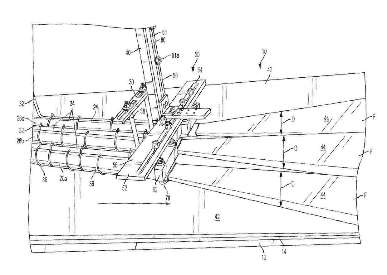
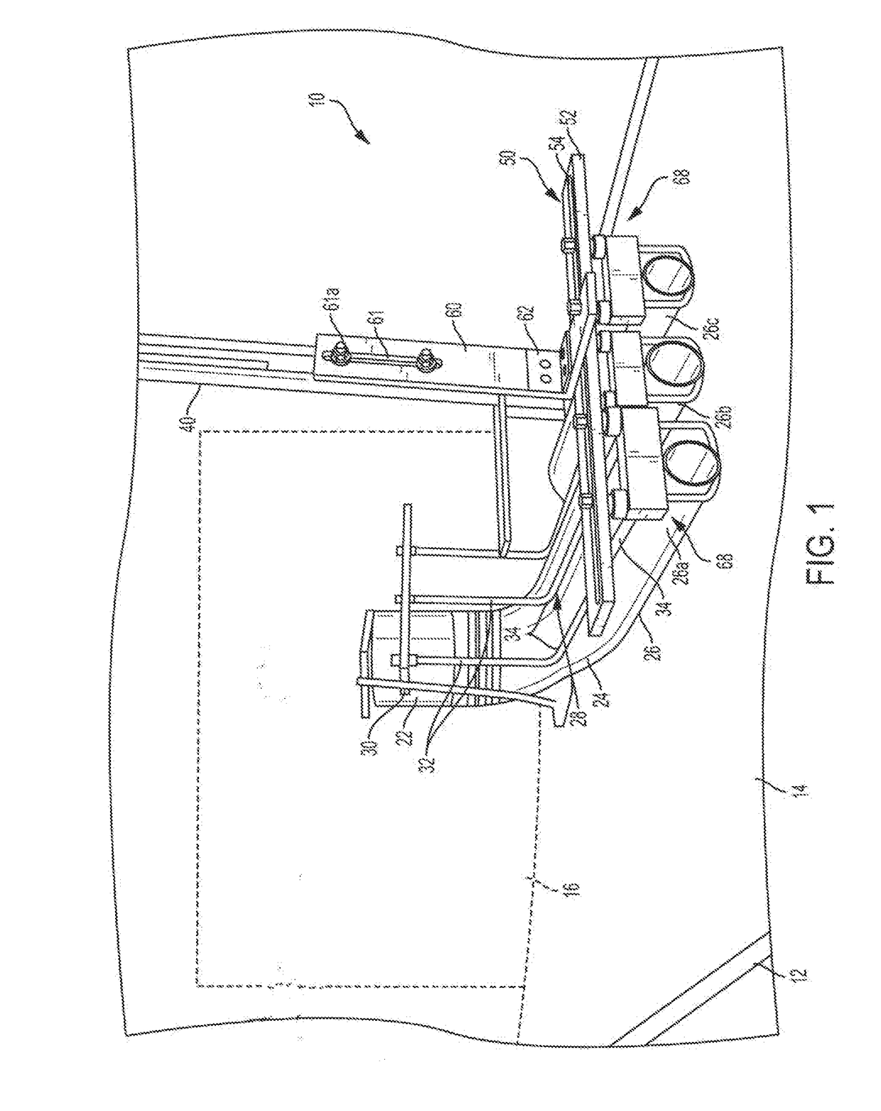
[0022]Referring now to FIG. 1, a gypsum wallboard production line is generally designated 10. As is known in the art, a support table 12 supports a moving endless conveyor belt 14. A slurry mixer 16 (shown schematically) is fixed in elevated relationship to the belt 14 and is similar to the mixers described in the patents identified above and incorporated by reference. Also as known in the art, an outlet boot 24 is securely mounted to the mixer outlet 22 and has at least one and preferably two or three outlet legs 26, presently designated 26a, 26b and 26c.

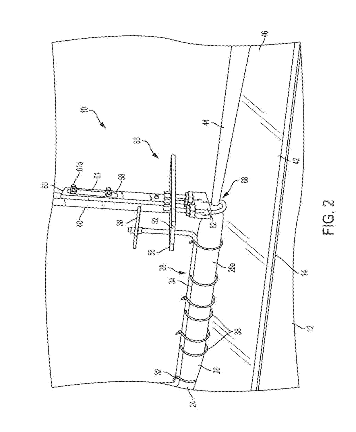
[0023]Referring now to FIGS. 1 and 2, support for the outlet boot 24 is provided by an outlet boot bracket 28, including a ring 30 located near to, and optionally surrounding the mixer outlet 22, and a plurality of generally “U”-shaped support rods 32. Elongate portions 34 of the rods 32 are each secured to one of the outlet legs 26a, 26b, 26c preferably using cable ties or other suitable fasteners 36 (FIG. 2). Opposite the ring 3...


PUM


Abstract

A gypsum slurry modifier device is provided for use with a gypsum mixer outlet boot having at least one tubular outlet leg, and includes a support bracket mountable to the outlet boot; at least one clamp member associated with the support bracket and constructed and arranged for engaging the at least one tubular outlet leg of the outlet boot. Each at least one clamp member is constructed and arranged for exerting a vertical compression force on the associated at least one tubular outlet leg for expanding a slurry outlet flow from the at least one leg laterally beyond an exterior surface of the leg.

Description

BACKGROUND[0001]The present invention relates to the production of gypsum wallboard, and more specifically, to devices for modifying the flow of gypsum slurry upon a moving conveyor line.[0002]It is well known to produce gypsum products (i.e., products comprising calcium sulfate dihydrate) from starting materials comprising calcined gypsum (i.e., calcium sulfate hemihydrate) and water. A popular application of gypsum chemistry is in the production of gypsum wallboard panels. The basic technology of gypsum wallboard panel manufacture is disclosed in U.S. Pat. Nos. 1,500,452; 2,207,339 and 4,009,062 all of which are incorporated by reference. In this process, calcined gypsum is uniformly dispersed in water to form a slurry, and then the slurry is deposited upon a continuously moving web of facing paper located on a conveyor line. After deposit upon the face paper, a top layer of backing paper is deposited upon the slurry, which is then cast into a desired shape and allowed to set to f...

Claims


Application Information

Patent Timeline
Patent Type & Authority Applications(United States)
IPC IPC(8): B05B1/32B05B15/04B01F15/02F16L3/10F16L3/00
CPCB05B1/326B01F15/0297B01F2215/0047F16L3/1091B05B15/04F16L3/003B28B19/0092F16K7/061F16L3/227B05B7/149B05B15/68B05C5/0225B05C11/00B28B13/0275F16L3/221B28B2013/0265B01F35/7549B01F2101/28
Inventor TODD, BRADRAGO, WILLIAM
Owner UNITED STATES GYPSUM CO
Why Eureka
Try Eureka