
Converter with oscillator and a system of converter with oscillator coupled with a load

a technology of converters and oscillators, which is applied in the field a system of converters with oscillators coupled with loads, can solve the problems of increasing the capacity of closely related coils and the relative losses tend to be higher, and achieves the effect of prolonging the time of their action on the connected loads

Active Publication Date: 2020-01-28
NAMI TECH SRO
View PDF3 Cites 0 Cited by
  • Summary
  • Abstract
  • Description
  • Claims
  • Application Information

AI Technical Summary

Benefits of technology

The invention is a converter with an oscillator that modifies the flow of voltage and current on the output of the converter and prolongs the time of their action on the connected loads. The patent describes an embodiment of the oscillator circuit that allows for easy connection of a system of capacitors and achieves the required overall capacitance of the oscillator circuit. The CL-LC type of oscillator circuit is shown to have the most favouable effect on the load after being connected. The patent also explains that the flow through the oscillator in the CL connection is easier, and mutual influence of impulses due to the inductive coupling of the bifilar coil occurs.

Problems solved by technology

Electricity converters mostly operate with very good efficiency with losses around 5-10% around the operating point however when the device is unloaded the relative losses tend to be higher.
A drawback is, of course, the increase of capacity of such closely related coils.

Method used


Image

  • Converter with oscillator and a system of converter with oscillator coupled with a load
  • Converter with oscillator and a system of converter with oscillator coupled with a load
  • Converter with oscillator and a system of converter with oscillator coupled with a load

Examples


Embodiment Construction

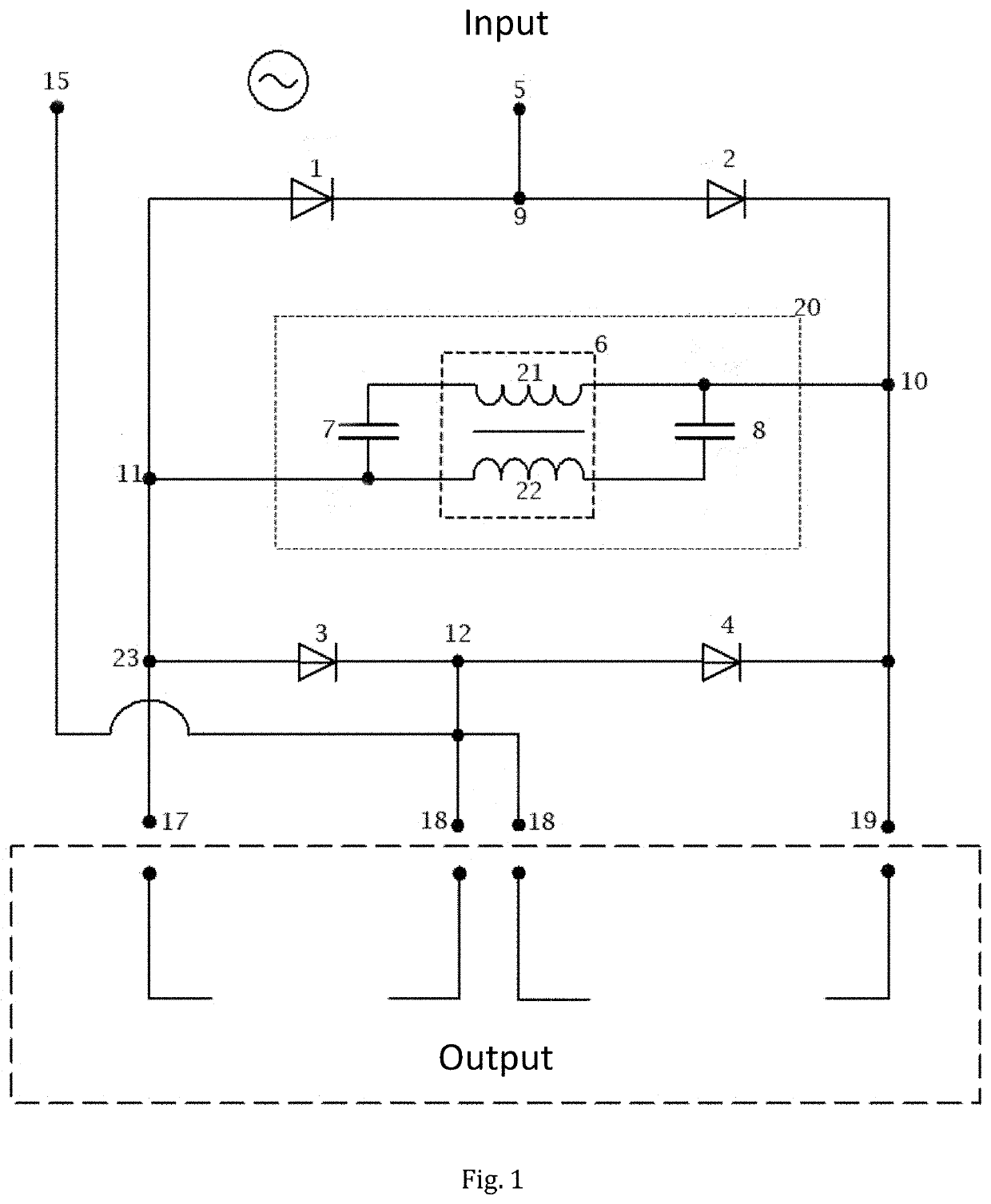
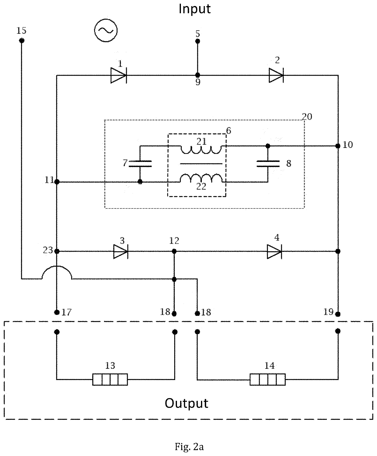
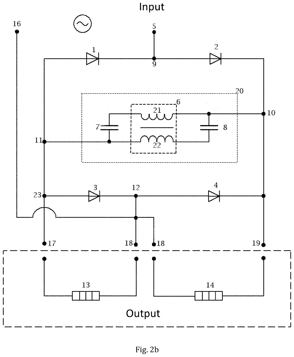
[0064]The scheme of connection of the converter with the CL-LC type of an oscillator in an exemplary embodiment is illustrated in the FIG. 1a. At the first phase input terminal 5 of the converter the phases of converter with oscillator are parallelly connected through the first node 9 to the cathode of the first diode 1 as well as to the anode of the second diode 2, where the first diode 1 has the anode connected through the third node 11 to the anode of the third diode 3 as well as to the first output terminal 17 of the converter, wherein the cathode of the third diode 3 is connected through the fourth node 12 to the anode of the fourth diode4 as well as to the neutral conductor 15 (FIG. 1a) or to the second phase input terminal 16 (not shown) of the converter and also to the second output terminal 18 of the converter, wherein the fourth diode 4 has the cathode connected to the third output terminal 19 of the converter as well as to the cathode of the second diode 2 via the second ...


PUM


Abstract

Converter with oscillator characterized in that it comprises an input for connecting the phase through a first node to cathode of a first diode as well as to anode of a second diode, where the first diode has anode connected through a third node to anode of a third diode as well as to a first output, wherein cathode of a third diode is connected through a fourth node to the anode of a fourth diode as well as to neutral conductor or to a second phase as well as to a second output, wherein the fourth diode has an anode connected to a third output and through a second node to the cathode of the second diode, wherein parallelly to the second node and to the third node at least one oscillator circuit comprising a bifilar coil with a first winding and a second winding and at least one capacitor is connected. Another object of the invention is a system comprising a converter with oscillator and a load as well as a three-phase system.

Description

CROSS-REFERENCE TO RELATED PATENT APPLICATIONS[0001]This application is a U.S. National Phase Application under 35 U.S.C. § 371 of International Patent Application No. PCT / CZ2015 / 000150, filed Dec. 10, 2015, and claims the priority of PV 2014-885, filed Dec. 10, 2014, all of which are incorporated by reference in their entireties. The International Application was published on Jun. 16, 2016 as International Publication No. WO 2016 / 091234 A1.FIELD OF THE INVENTION[0002]The invention relates to a converter comprising LC, LC-LC or LC-CL oscillator with inductive coupling of bifilar coil connected at the middle of the Graetz bridge, which modifies the flow of voltage and current at the output and prolongs their action when the converter is coupled with a load. Further, the invention relates to a system of converter and load comprising the aforesaid converter and at least two loads.BACKGROUND OF THE INVENTION[0003]In electrical engineering, a converter represents a device intended for ch...

Claims


Application Information

Patent Timeline
Patent Type & Authority Patents(United States)
IPC IPC(8): H02M7/06H03B5/18H02M3/28H02M1/44H02M1/12
CPCH02M1/44H02M7/064H03B5/18H02M1/126H02M7/066H02M3/28
Inventor ODLO{HACEK OVER (Z)}ILÍK, MIROSLAVZR{DOT OVER (U)}NA, DALIMILZR{DOT OVER (U)}NA, MARTIN
Owner NAMI TECH SRO
Learn More