Hydrogen supply for micro fuel cells

a fuel cell and micro-fuel technology, applied in the field of micro-fuel cells, can solve the problems of limited energy stored in the battery, major inconvenience of the battery, and limited amount of stored energy

Inactive Publication Date: 2007-11-01
MOTOROLA INC
View PDF11 Cites 14 Cited by
  • Summary
  • Abstract
  • Description
  • Claims
  • Application Information

AI Technical Summary

Benefits of technology

[0010] A compact and efficient storage apparatus contains a fuel source and water for supplying hydrogen fuel to a micro-fuel cell. The storage apparatus comprises a housing defining a fuel source chamber and a plurality of water chambers, and one or more polymer crystals containing water positioned within each of the water chambers. The fuel source, such as a chemical

Problems solved by technology

The energy stored in the batteries is limited.
The limited amount of stored energy and the frequent recharging are major inconveniences with the batteries.
However, the energy generated by these methods is small, usually only a few milliwatts, and it requires a large volume to generate sufficient power in the hundred of milliwatts needed, making it unattractive for cell phone type applications.
However, the power densities are low with this approach, and also there are safety concerns with the radioactive materials.
This is an attractive power source for remote sensor type applications, but not for cell phone power sources.
Fuel cells with active control systems and high operating temperature fuel cells such as active control direct methanol or formic acid fuel cells (DMFC or DFAFC), reformed hydrogen fuel cells (RHFC) and solid oxide fuel cells (SOFC) are complex systems and very difficult to miniaturize to the 2-5 cc volume needed for cell phone application.
However, in addition to the miniaturization issues, other concerns include supply of hydrogen for hydrogen fuel cells, life time and energy density for passive DMFC and DFAFC, and life time, energy density and power density with biofuel cells.
Most development activities on small fuel

Method used


Image

  • Hydrogen supply for micro fuel cells
  • Hydrogen supply for micro fuel cells
  • Hydrogen supply for micro fuel cells

Examples


Embodiment Construction

[0019] The following detailed description of the invention is merely exemplary in nature and is not intended to limit the invention or the application and uses of the invention. Furthermore, there is no intention to be bound by any theory presented in the preceding background of the invention or the following detailed description of the invention.

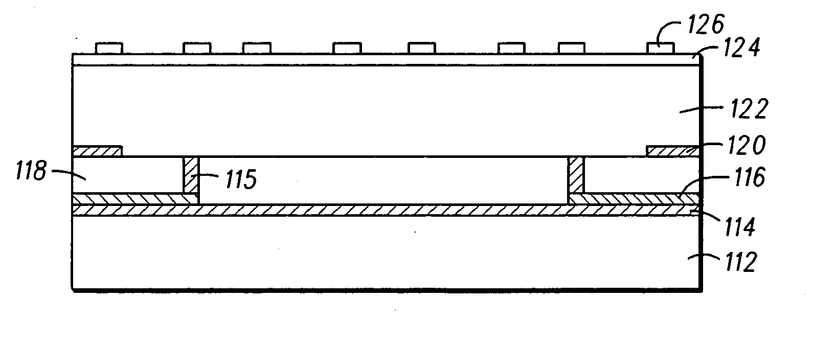
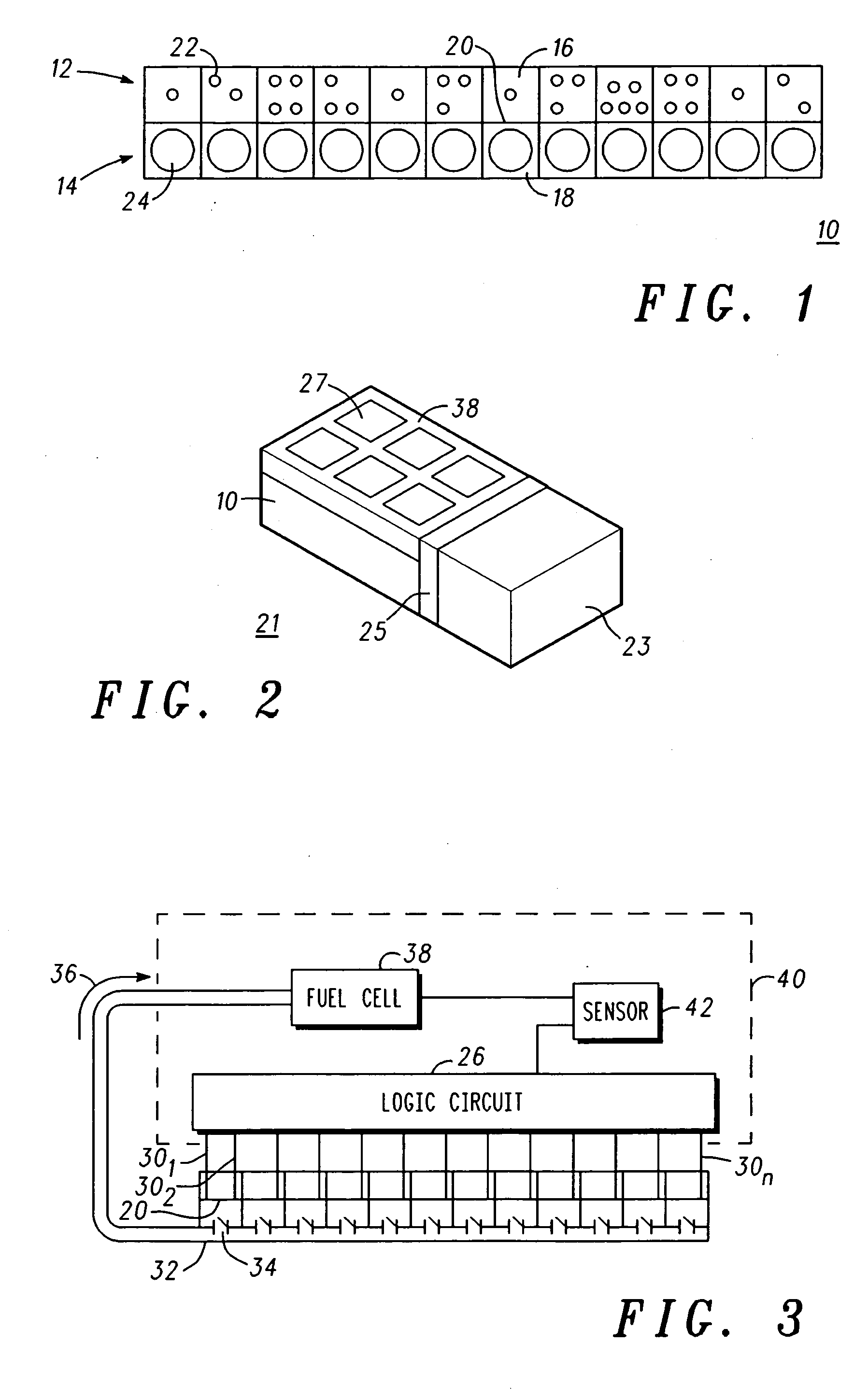
[0020] A high energy density fuel source and controlled delivery of the fuel for a micro-fuel cell is described herein. Water is stored in super adsorbent polymer crystals, or a hydro gel material, within a plurality of chambers. Each of the chambers are selectively “opened” so the water may migrate and mix with a solid fuel to provide hydrogen at a low temperature and at a low rate to a micro-fuel cell. The fuel is dense and compact, thereby conserving space, and the water is conveniently packaged for long term storage. The choice of the fuel (solid fuel source), the other reactant (which is water) in a convenient form (adsorbed in a poly...


PUM


Abstract

A disposable, compact, and efficient storage apparatus (10) contains a fuel source (24) and water for supplying hydrogen fuel (36) to a micro-fuel cell. The storage apparatus comprises a housing defining a fuel source chamber (14) and a plurality of water chambers (12), and one or more polymer crystals (22) containing water positioned within each of the water chambers (12). The fuel source (24), such as a chemical hydride mixed with a catalyst, is positioned within the fuel source chamber (14), wherein the water in each of the water chambers (12) is selectively allowed to migrate to the fuel source chamber (14) to contact the solid fuel, thereby producing the hydrogen fuel (36) at a desired flow rate and temperature. A conduit (32) supplies the hydrogen fuel (36) produced within the housing to the fuel cell (38).

Description

FIELD OF THE INVENTION [0001] The present invention generally relates to micro-fuel cells and more particularly to a storage apparatus containing a fuel source and water for supplying hydrogen fuel to a micro-fuel cell. BACKGROUND OF THE INVENTION [0002] Rechargeable batteries are the primary power source for cell phones and various other portable electronic devices. The energy stored in the batteries is limited. It is determined by the energy density (Wh / L) of the storage material, its chemistry, and the volume of the battery. For example, for a typical Li ion cell phone battery with a 250 Wh / L energy density, a 10 cc battery would store 2.5 Wh of energy. It could last for a few hours to a few days depending on the usage. Recharging always requires an electrical outlet. The limited amount of stored energy and the frequent recharging are major inconveniences with the batteries. There is a need for a longer lasting, easily recharging solution for cell phone power sources. One approac...

Claims


Application Information

Patent Timeline
IPC IPC(8): B01J8/08H01M8/06
CPCH01M8/04201H01M8/04216H01M8/04589H01M8/04738Y02E60/525H01M8/065H01M8/1286Y02E60/521H01M8/04753Y02E60/50H01M8/04
Inventor KORIPELLA, CHOWDARY R.BEACCO, DAVE P.FISHER, ALLISON M.MYLAN, BILLY J.
Owner MOTOROLA INC
Why Eureka
Try Eureka