Solid product dispenser

Active Publication Date: 2007-11-01
ECOLAB USA INC
View PDF31 Cites 18 Cited by
  • Summary
  • Abstract
  • Description
  • Claims
  • Application Information

AI Technical Summary

Benefits of technology

[0006]In one aspect of the present invention, a solid product dispenser includes a first housing having a top, a first cavity, and a manifold within the first cavity. The top supports a bottom surface of a solid product having a first shape. The manifold has a first passageway, a second passageway, and a second cavity. A first diluent inlet is in fluid communication with the first passageway, and a second diluent inlet is in fluid communication with the second passageway and the second cavity. A spray nozzle is in fluid communication with the first passageway and the first cavity. A concentrated solution outlet is in fluid with the first cavity, and a diluent outlet housed within the concentrated solution outlet is in fluid communication with the second cavity. Preferably, the concentrated solution outlet and the diluent outlet are funnel-shaped, and the diluent outlet is nested within the cavity of the concentrated solution outlet. The diluent outlet preferably has a relatively small diameter to increase the rate of diluent flowing out of the diluent outlet. An outlet tube may be operatively connected to the concentrated solution outlet.
[0007]A diluent is supplied to the first inlet and the second inlet. From the first inlet, the diluent flows into the first passageway and into the spray nozzle, which sprays the diluent onto the bottom surface of the solid product to create a concentrated solution. The concentrated solution flows through the first cavity into the concentrated solution outlet. From the second inlet, the diluent flows into the second passageway, into the second cavity, and into the diluent outlet. The diluent flowing through the diluent outlet at a relatively fast rate creates a venturi effect to draw the concentrated solution out of the concentrated solution outlet. The concent

Problems solved by technology

Still further, when the additional diluent is added to the use solution, in prior art dispensers, there is often a problem of foami

Method used


Image

  • Solid product dispenser
  • Solid product dispenser
  • Solid product dispenser

Examples


Embodiment Construction

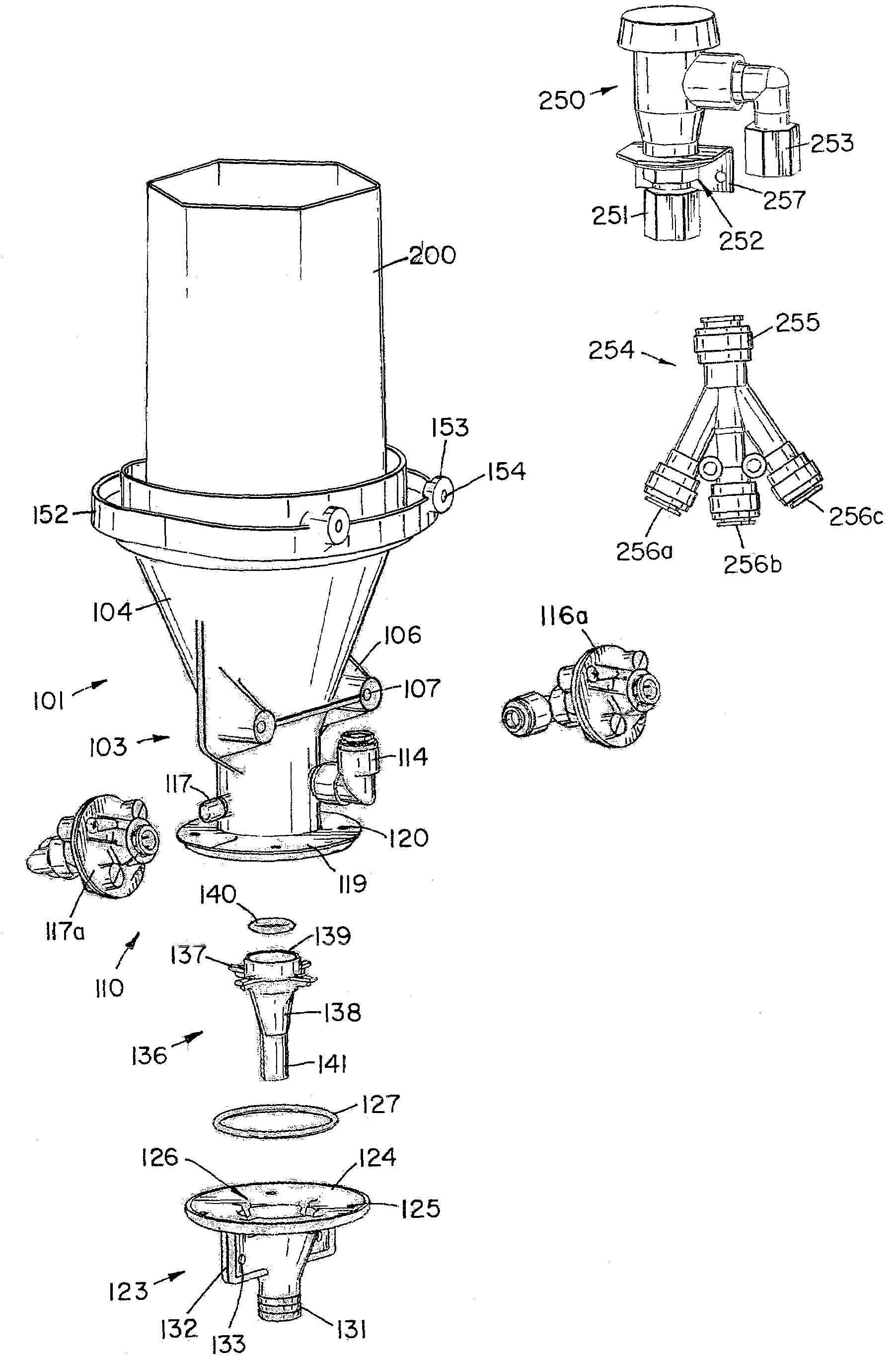
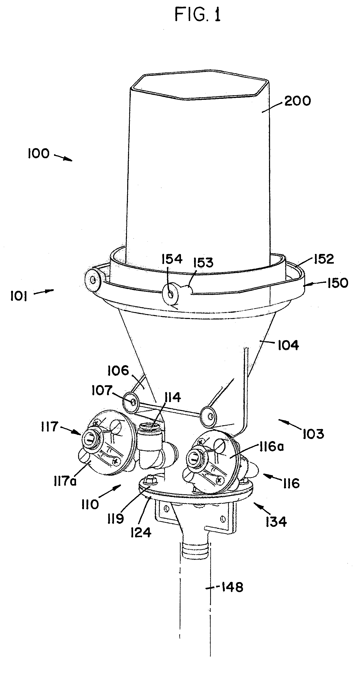
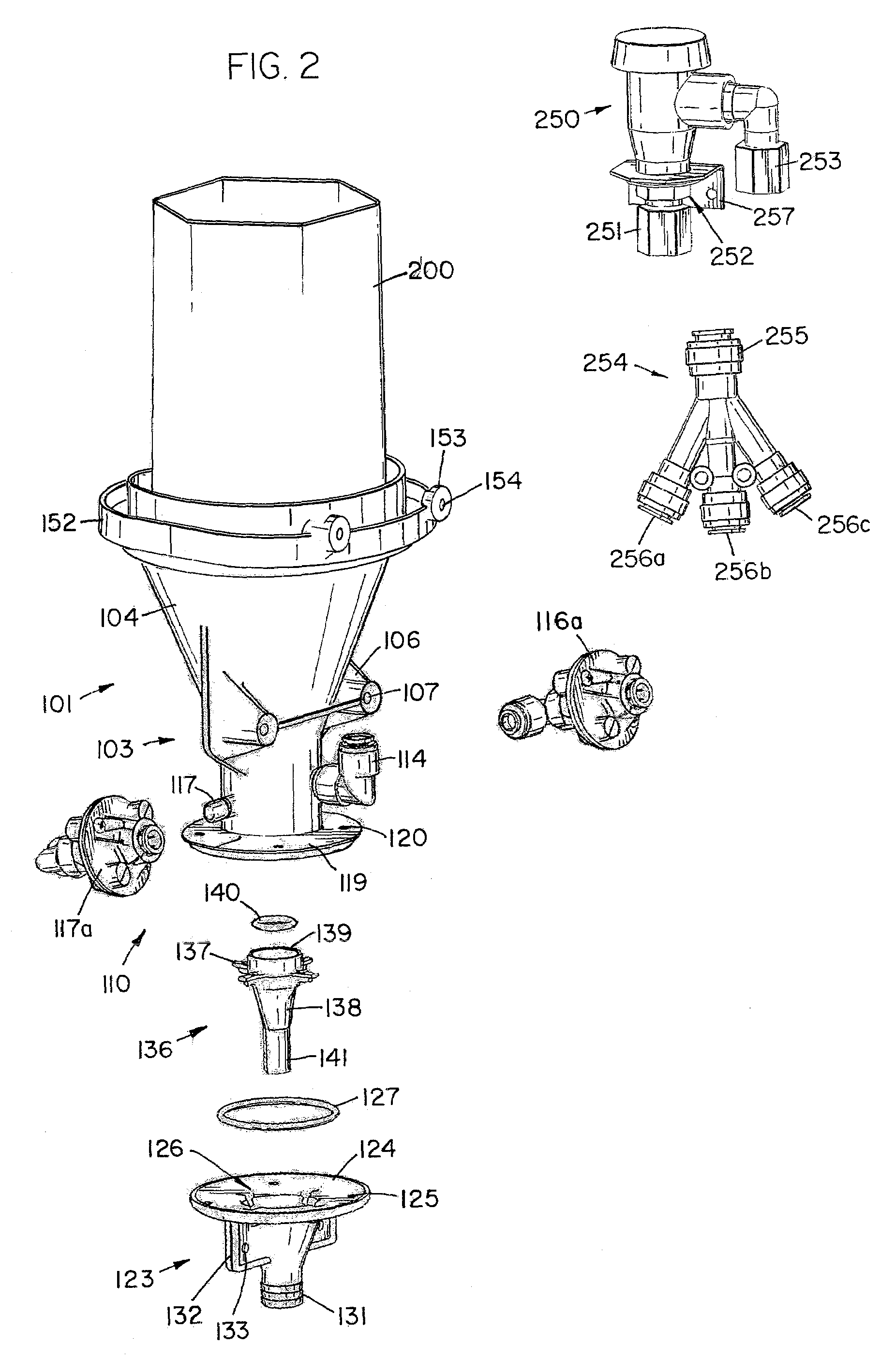
[0029]A preferred embodiment dispenser constructed according to the principles of the present invention is designated by the numeral 100 in the drawings.

[0030]As shown in FIGS. 1-4, the dispenser 100 includes a housing 101 having a bottom portion 103 and a top portion 200. The bottom portion 103 includes a conical portion 104, an inlet portion 110, an outlet portion 123, and a diluent outlet portion 136. The conical portion 104 has a top 150 and a conical-shaped cavity 105. The top 150 is preferably round and has a perimeter surface 151 with a flange 152 extending upward from proximate the outer edge of the perimeter surface 151. Thus, the perimeter surface 151 forms a ledge around the top 150 and the flange 152 forms a railing around the perimeter surface 151. As shown in FIG. 5, a product support 144′ includes elongate members 145′ and 146′ forming a grid supported by the perimeter surface 151 upon which product may be placed. The product support 144′ supports the product and allo...


PUM

PropertyMeasurementUnit
Temperatureaaaaaaaaaa
Lengthaaaaaaaaaa
Angleaaaaaaaaaa

Abstract

A solid product dispenser includes a housing and a product holder. The housing includes a concentrated solution outlet, a diluent outlet, and an outlet tube in which concentrated solution from the concentrated solution outlet and diluent from the diluent outlet are mixed to form a use solution. Proximate the housing and the product holder is an overflow outlet from which a vacuum breaker is at least 3.50 inches.

Description

[0001]This application claims the benefit of U.S. Provisional Patent Application 60 / 795,340 filed Apr. 27, 2006.FIELD OF THE INVENTION [0002]The present invention relates to a method and an apparatus for dispensing a solid product.BACKGROUND OF THE INVENTION [0003]Dispensers that utilize a diluent to erode a portion of a solid product such as an all purpose cleaning agent, a detergent, a sanitizer, a rinse aid, or any other suitable chemical from which it is desired to make a use solution are well known. The product being dispensed is typically a solid product and can take the form of either a solid block of chemicals, pellets, a cast product, or an extruded product. One example of such a dispenser is found in U.S. Pat. No. 4,826,661 by Copeland et al. This patent discloses a solid block chemical dispenser for cleaning systems. The dispenser includes a spray nozzle for directing a dissolving spray onto a surface of a solid block of a cleaning composition. The nozzle sprays on the ex...

Claims


Application Information

Patent Timeline
IPC IPC(8): B01D11/02
CPCA47L15/4436B01F1/0027B01F5/0413D06F39/02B01F2001/0061B01F2215/004B01F5/0496Y10T137/4891B01F21/4021B01F21/221B01F21/22B01F25/312B01F25/316B01F35/2115B01F35/2211B01F35/718051B01F2101/24
Inventor LIMBACK, SCOTT R.BERG, THOMAS P.WILLIAMS, KRISTINE J.CARLSON, BRIAN P.
Owner ECOLAB USA INC
Why Eureka
Try Eureka