Wireless control for dental equipment

a technology for controlling devices and dental equipment, applied in the field of dental instruments, can solve the problems of reducing the efficiency of dental procedures, complexity and clutter in the environment, and the cable can be a potential hazard for both the dental professional and the patient, and achieves the effects of convenient adjustment, convenient adjustment, and flexible equipment control

Inactive Publication Date: 2007-11-01
DISCUS DENTAL LLC
View PDF4 Cites 63 Cited by
  • Summary
  • Abstract
  • Description
  • Claims
  • Application Information

AI Technical Summary

Benefits of technology

[0008] The wireless control, such as the foot switch, replaces manual and foot operated controls formerly connected by cables to the dental tool and / or to the power supply. This removes a potential safety hazard in the dentist's office and makes the equipment control more versatile and easier to adapt to various office conditions.
[0009] In another exemplary embodiment of the invention, the dental tool comprises a base unit, a handpiece comprising a handle, a dental insert and a wireless control switch such as a foot switch. The dental tool is connected to a power, and / or fluid, and / or an air supply source through a conduit cable, so that the supply source, though coupled to the tool, is located at a position remote from the working end of the tool. The wireless foot switch, in the form of such as a pedal, is located within easy reach of the operator to permit turn-on and / or turn-off of the tool. The signaling means which simply and yet effectively provides for selective automatic turn on and turn off of the tool while totally eliminating the need for an electrical connection between the main supply unit and the remote control unit again removes a potential safety hazard in the dentist's office and makes the equipment control more versatile and easier to adapt to various office conditions. In addition to controlling the on and off of the dental tool, the wireless module can also be programmed to control the speed of the tool by a switch on the tool.

Problems solved by technology

The cables can be a potential hazard to both the dental professional and patient.
In addition, the complexity and clutter tends to reduce the efficiency of dental procedures by slowing the activities of the dental professional.
Complexity and clutter in the environment also increases the risk of error and accident.

Method used


Image

  • Wireless control for dental equipment
  • Wireless control for dental equipment
  • Wireless control for dental equipment

Examples


Embodiment Construction

[0037] Conventional ultrasonic units have a footswitch connected to the unit with a cable. When the foot control is depressed, a solenoid valve is activated permitting the flow of water and electricity through the regulator and through the solenoid, to the handpiece and over the dental insert or tip. Vibration of the insert is thus initiated by energizing the ultrasonic generation mechanism.

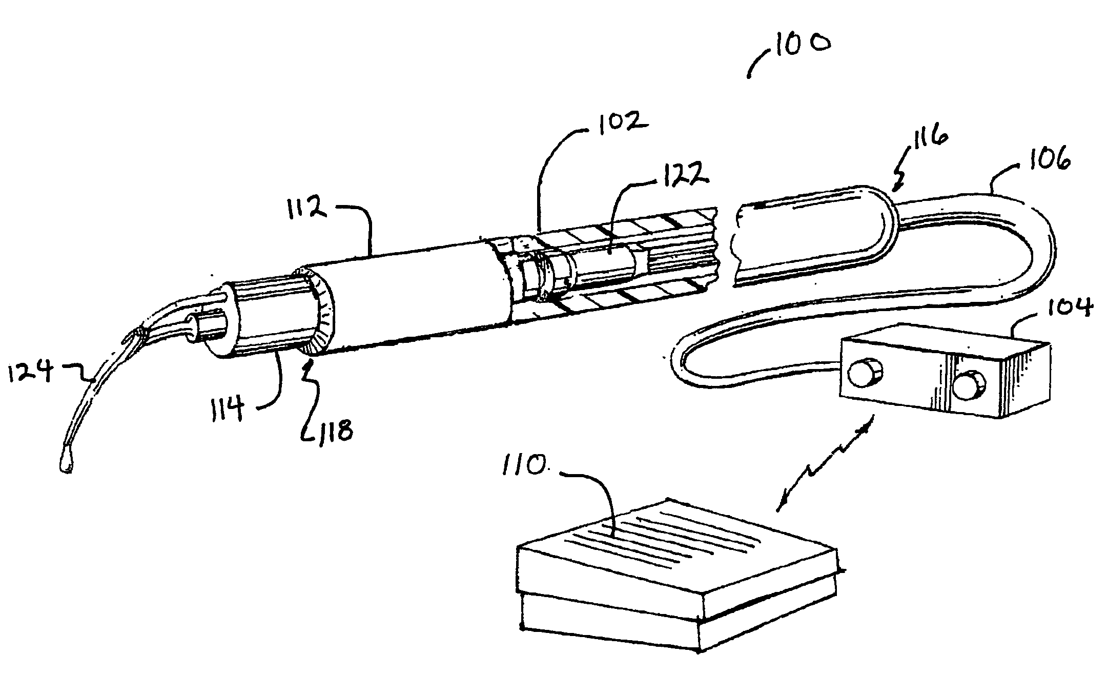
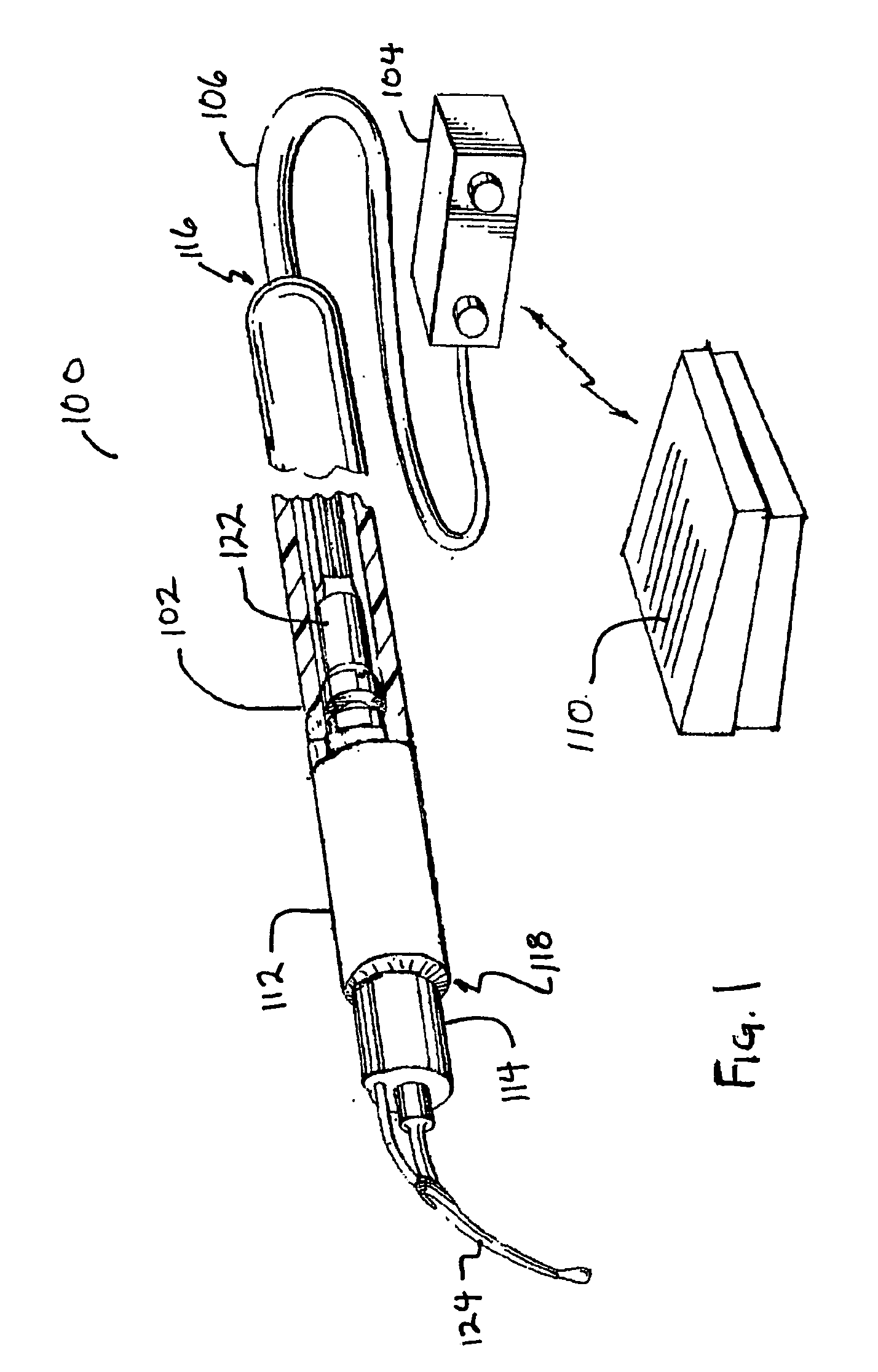
[0038]FIG. 1 illustrates an embodiment of the present invention in the form of an ultrasonic dental system 100 including an ultrasonic dental tool 102 attached to an electrical energy & fluid source 104, via a cable 106 along with a wireless control switch, shown here as a wireless foot pedal 110, conveniently disposed within easy reach by the dental professional. The cable 106 includes a conduit for carrying fluid as well as wires for carrying electrical power and signals from the electrical energy and fluid source 104 to the ultrasonic dental tool 102. The ultrasonic dental tool 102 includes a...


PUM


Abstract

The present invention relates to a wireless remote control for dental equipment, such as dental scaler tools, dental drills, prophy angles and other rotary instruments. The wireless control switch can control the on and off state of the dental tool, or it can also be programmed to control the speed of the tool by a switch on the tool. The wireless control switch can be in the form of, for example, a foot switch, and replaces manual and foot operated controls formerly connected by cables to the dental tools. This removes a potential safety hazard in the dentist's office and makes the equipment control more versatile and easier to adapt to various office conditions. The wireless control can be battery powered, further eliminating the need for cables.

Description

CROSS-REFERENCE TO RELATED APPLICATIONS [0001] The present application is the National Stage of International Application No. PCT / US2004 / 039937 designating the United States, filed on Nov. 24, 2004, which claims the benefit under 35 U.S.C. 119(e) of U.S. Provisional Patent Application No. 60 / 524,911, filed on Nov. 26, 2003, the disclosures of which are herewith incorporated by reference in their entirety.FIELD OF THE INVENTION [0002] The present invention relates to dental instruments and more particularly to control devices for dental instruments. BACKGROUND OF THE INVENTION [0003] Many tools are operated by electrical power in a dentist's office. Unless they are battery powered, such tools are tethered and connected to the electrical source by cables. Since most power inlets are installed around the walls of a dentist's office, such cables traverse the room where dental procedures are performed. Some tools are operated by manual foot pedals, which are also connected by cables to t...

Claims


Application Information

Patent Timeline
Patent Type & Authority Applications(United States)
IPC IPC(8): A61C1/02
CPCA61C1/0015A61C1/0023A61C17/20A61C5/02A61C17/16A61C3/025A61C5/40A61C2204/002
Inventor ROSENBLOOD, KENNETHLEVY, HAIMATKIN, BENQUAN, NANCY N.
Owner DISCUS DENTAL LLC
Why Eureka
Try Eureka