Grinding Wheel

a technology of grinding wheel and grinding head, which is applied in the direction of grinding head, gear teeth, gear teeth, etc., can solve the problems of replacing the whole grinding wheel, and achieve the effect of preventing thermal deformation and simplifying the manufacturing process of the abrasive segmen

Inactive Publication Date: 2007-11-01
PARK RIN SOON
View PDF12 Cites 58 Cited by
  • Summary
  • Abstract
  • Description
  • Claims
  • Application Information

AI Technical Summary

Benefits of technology

[0009] Like this, since the abrasive segment is formed in a body by pressurizing and sintering diamond-metal mixed powders and metal powders, it is possible to simplify a manufacturing process of the abrasive segment and to prevent a thermal deformation which can occur during the welding operation.
[0010] In the me...

Problems solved by technology

In particular, even when some of the abrasive segments 2 are in...

Method used


Image

  • Grinding Wheel
  • Grinding Wheel
  • Grinding Wheel

Examples


Embodiment Construction

[0019] Hereinafter, a preferred embodiment of the present invention will be described with reference to the accompanying drawings. In the following description of the present invention, a detailed description of known functions and configurations incorporated herein will be omitted when it may make the subject matter of the present invention rather unclear.

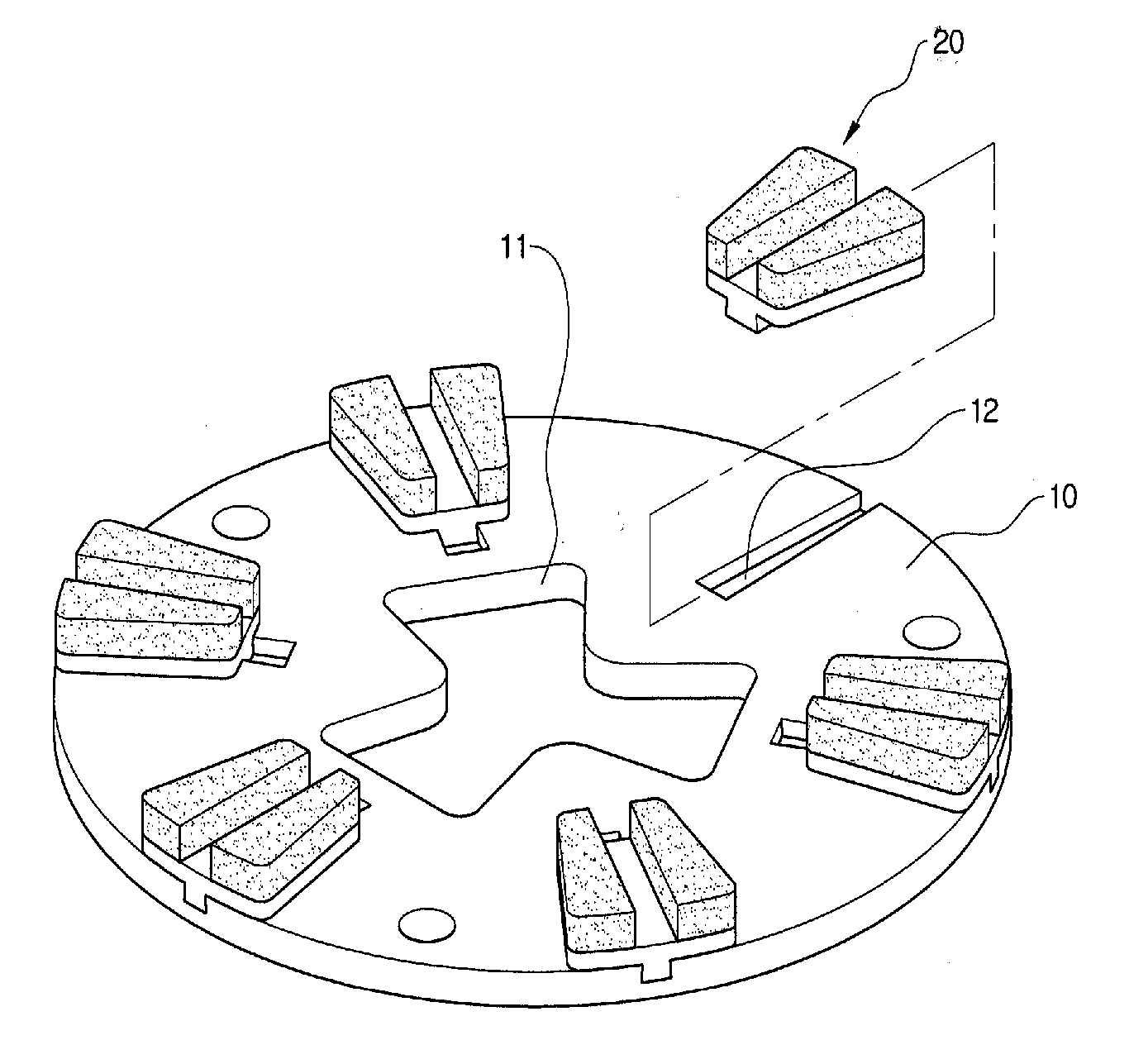
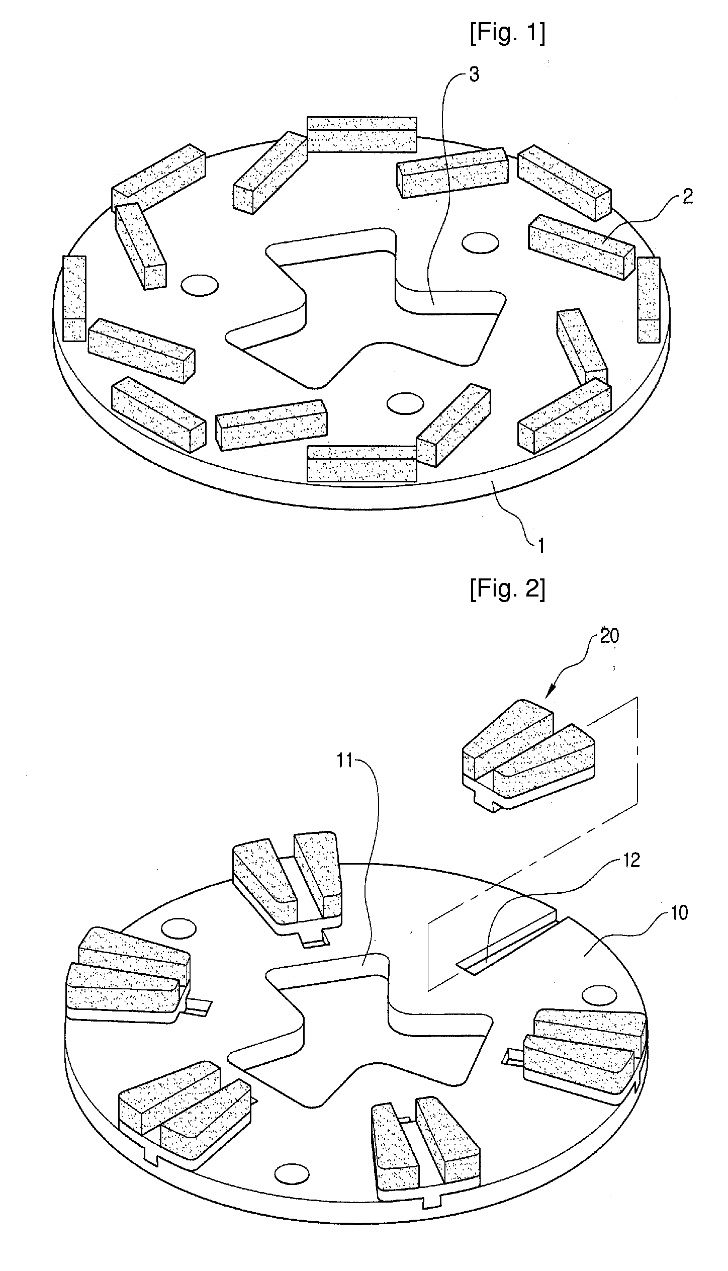
[0020] As shown in FIG. 2, a grinding wheel according to an embodiment of the invention comprises a disc 10 and a plurality of abrasive segments 20 radially connected to a surface of the disc 10 at an interval. A connection hole 11 is formed at a center of the disc, to which a rotation axis of a grinder (not shown) is connected.

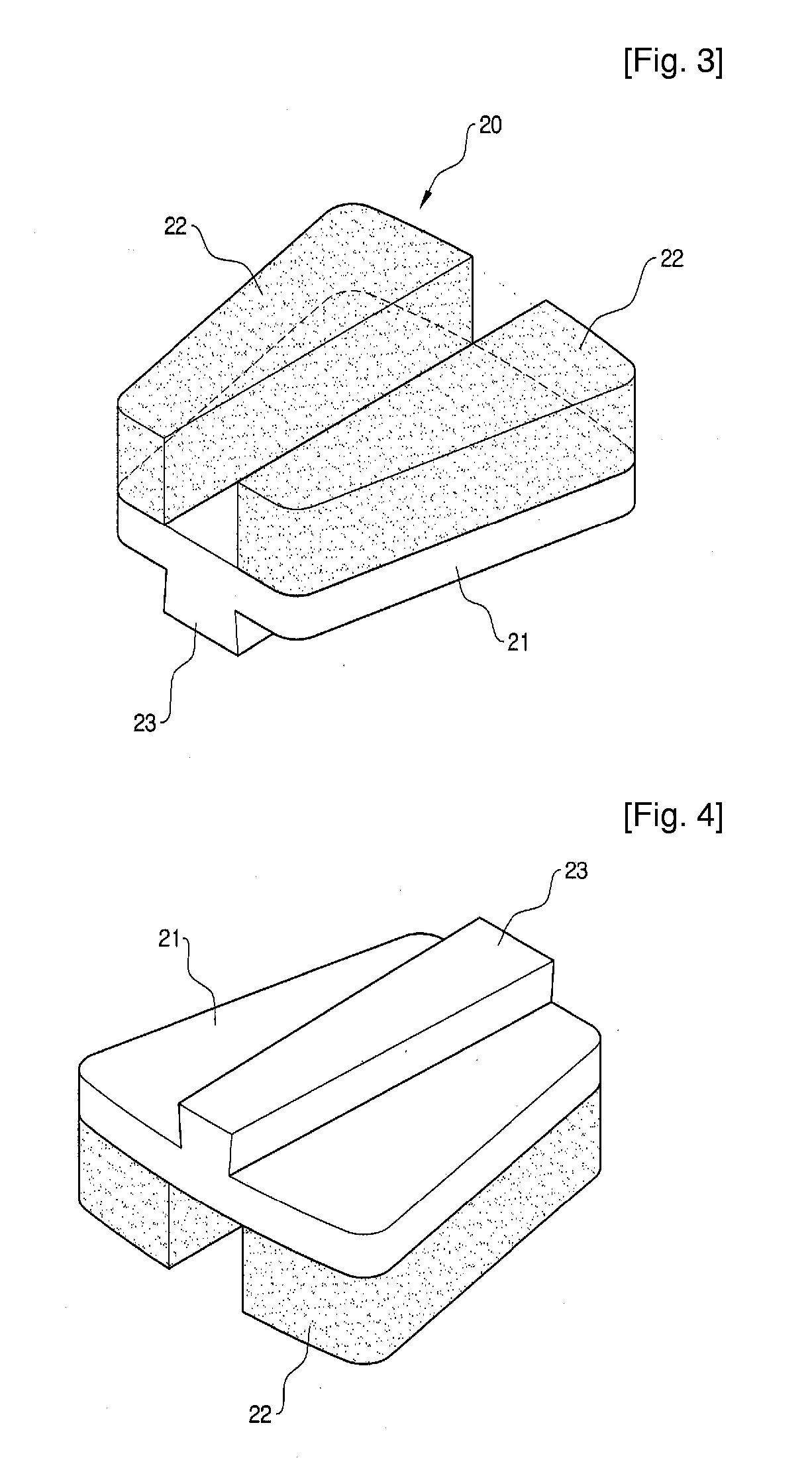
[0021] As shown in FIG. 3, the abrasive segment 20 includes a base part 21 having a shape which is generally similar to a trapezoid and a pair of tips 22 having a shape which is approximately similar to a right-triangle, and symmetrically bonded to an upper surface of the base part 21. The tip 22 is made ...


PUM

PropertyMeasurementUnit
Shapeaaaaaaaaaa
Widthaaaaaaaaaa
Efficiencyaaaaaaaaaa

Abstract

A grinding wheel has a disc having a connection hole formed at a center thereof, to which a rotation axis of a grinder is connected, and a plurality of abrasive segments detachably connected to a surface of the disc. A plurality of fixing recesses are radially formed on the surface of the disc at an interval and fixing protrusions having a shape corresponding to the fixing recess are formed on bottom surfaces of the abrasive segments, so that the abrasive segments are connected to the disc by inserting the fixing protrusions into the fixing recesses. According to the grinding wheel, when the abrasive segment is worn away or inferior as it is used for a long time, it has only to replace the corresponding abrasive segment only. Accordingly, an economical efficiency is high.

Description

TECHNICAL FIELD [0001] The present invention relates to a grinding wheel used for grinding a surface of a rigid material such as stone, and more particularly to a grinding wheel having an abrasive segment formed by mixing, molding and sintering metal and diamond powders. BACKGROUND ART [0002] As shown in FIG. 1, a grinding wheel according to the prior art comprises a disc 1 and a plurality of abrasive segments 2 radially provided to a surface of the disc 1 at an interval. The grinding wheel is generally connected to a rotation axis of an electrically powered grinder (not shown) and rotated to perform an abrading operation as the grinder is driven while the abrasive segments 2 are in contact with a surface of an object to be abraded. In order to connect the wheel to the grinder, there is formed a connection hole at a center of the disc 1, to which the rotation axis of the grinder is connected. [0003] The abrasive segment 2 is made by mixing diamond powders with metal powders such as ...

Claims


Application Information

Patent Timeline
IPC IPC(8): B24B25/00B24D7/06B24D5/06
CPCB24B41/047B24D7/066B24D5/06
Inventor PARK, RIN-SOON
Owner PARK RIN SOON
Why Eureka
Try Eureka