
Middle ear prosthesis

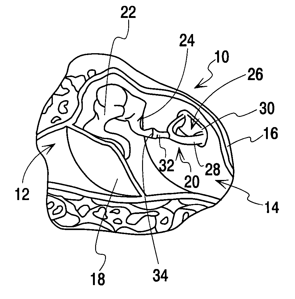
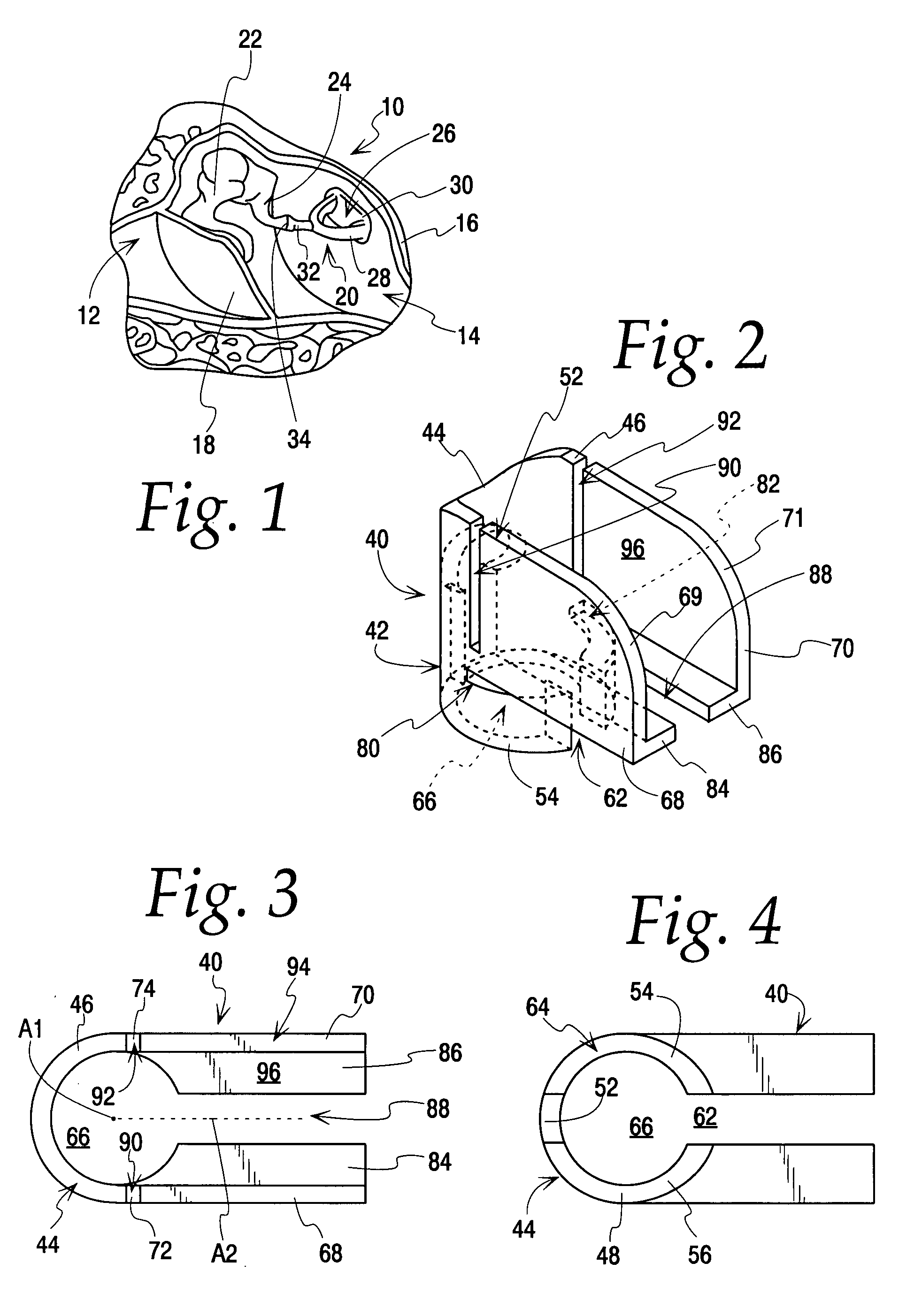
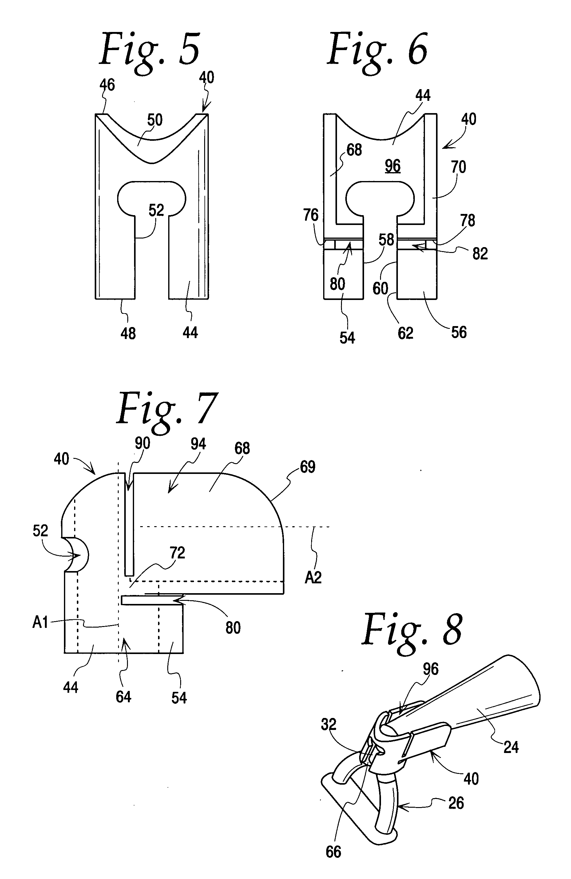
a middle ear and prosthesis technology, applied in the field of ossicular prosthesis, can solve the problems of conductive hearing loss, inability to easily adapt to custom, inability to fix or crimp an ossicular prosthesis to bone, etc., and achieve the effect of facilitating the reception of the head

Active Publication Date: 2007-11-01
CLARITY
View PDF20 Cites 28 Cited by
  • Summary
  • Abstract
  • Description
  • Claims
  • Application Information

AI Technical Summary

Benefits of technology

[0013] According to a second embodiment of the invention, an ISJ prosthesis is provided including first and second slotted tubular portions perpendicularly arranged relative to each other. The first slotted tubular portion includes one or more wall portions that are opened and the second slotted tubular portion includes fingers that are opened. The wall portions and fingers are deformed about the stapes and incus, preferably by the application of heat, to stably hold the stapes and incus in the desired anatomical relationship.
[0014] According to third embodiment of the invention, an angular piston prosthesis is provided in which a slotted tubular portion is provided on a rod element. The slotted tubular portion includes one or more arms that can be deformed about the incus, such as by applicatio

Problems solved by technology

The result is a conductive hearing loss related to the disrupted ossicular chain.
Also, the hydroxylapatite material is inherently fragile, prone to breakage and cannot be easily modified to custom fit the incus or stapes head.
Fixating or crimping an ossicular prosthesis to bone can be difficult due to problems with prosthesis stability, surgical exposure, appropriate clamping, etc.
However, such a bight structure is ineffective for coupling various ossicular bones together, either because of the anatomy or because of the lack of the stability provided.

Method used


Image

  • Middle ear prosthesis
  • Middle ear prosthesis
  • Middle ear prosthesis

Examples


second embodiment

[0049]FIGS. 9-12 illustrate an ISJ prosthesis 100 according to the invention. The ISJ prosthesis 100 differs from the ISJ prosthesis 40, discussed above, in that its design is more particularly adapted for “self-crimping”. The ISJ prosthesis 100 is manufactured of a unitary body of a shape memory material. The shape memory material may be a shape memory alloy, such as Nitinol, or a shape memory polymer, such as Calo-MER (The Polymer Technology Group, Berkeley, Calif.). With such a shape memory material, a portion of a prosthesis body can be deformed into an open configuration to provide spacing to allow the prosthesis to be placed over one or more bones, and when heat is applied to the prosthesis, the prosthesis self closes to lock around the bone structure.

[0050] Nitinol is a shape memory alloy that has proven biocompatibility. It can be manufactured via established means. The “memory” of the material is set while the material is in its martensitic phase. During this “shape setting...

embodiment 304

[0059]FIG. 22 illustrates an adjustable length prosthesis 320, similar to the prosthesis 300 of FIG. 18, with the head removed, according to an alternative embodiment of the invention. In this embodiment, the prosthesis 320 includes a shaft 322 and a cup 324. The cup does not open as in the embodiment 304, above. Instead, a tab 326 is provided for locking the arch of a stapes when received in rounded notches 328. The tab 326 is shown in the shape set position in FIG. 22. FIG. 23 illustrates the tab 326 deformed for packaging. During the operation, the stapes head is received in the cup 324, with the arches resting in the notches 328. The shaped memory material is heat activated such that the tab 326 returns to the position of FIG. 22, extends through the stapes arch and under the capitulum of the stapes dead to grasp and retain the stapes.


PUM


Abstract

A middle ear prosthesis comprises a body of deformable material capable of retaining different shapes. The body comprises a slotted wall defining a cavity for receiving a bone of the middle ear. The wall is deformable proximate slots in the wall between an open position for receiving the bone and a closed position wherein the body is reshaped to grasp the bone.

Description

CROSS REFERENCE [0001] This application is a continuation-in-part of Ser. No. 10 / 976,638, filed Oct. 29, 2004, and a continuation-in-part of Ser. No. 11 / 428,672, filed Jul. 5, 2006, which is a continuation of U.S. Ser. No. 10 / 666,451, filed Sep. 19, 2003, now issued as U.S. Pat. No. 7,087,081, and claims benefit of both Ser. Nos. 60 / 823,914, filed Aug. 30, 2006, and 60 / 853,938, filed Oct. 24, 2006.FIELD OF THE INVENTION [0002] This invention relates to an ossicular prosthesis used for replacement and reconstruction and, more particularly, to a middle ear prosthesis of a deformable material. BACKGROUND OF THE INVENTION [0003] Due to disease, trauma, or congenital malformation, the ossicles of the middle ear are sometimes damaged. The delicate joint between the incus and the stapes is termed the incudo-stapedial joint (ISJ). The ISJ is a cartilaginous joint having a tendency to ossify in older humans. When the joint is interrupted due to erosion of the joint or the incus itself, vibra...

Claims


Application Information

Patent Timeline
IPC IPC(8): A61F2/18
CPCA61F2/18A61F2250/0007A61F2002/183
Inventor REITAN, HARLAN J.WHITE, MICHAEL D.PRESCOTT, ANTHONY D.IRELAND, J. PATRICKBRIGGS, CASPERBROSNAHAN, ROBERT
Owner CLARITY
Learn More