
System and method to power route hierarchical designs that employ macro reuse

a hierarchical design and power routing technology, applied in the field of circuit fabrication, can solve the problems of blockage of channels five and six, inability to wire signals, and increased cost of rlm re-use in additional area

Inactive Publication Date: 2007-11-01
IBM CORP
View PDF10 Cites 96 Cited by
  • Summary
  • Abstract
  • Description
  • Claims
  • Application Information

AI Technical Summary

Benefits of technology

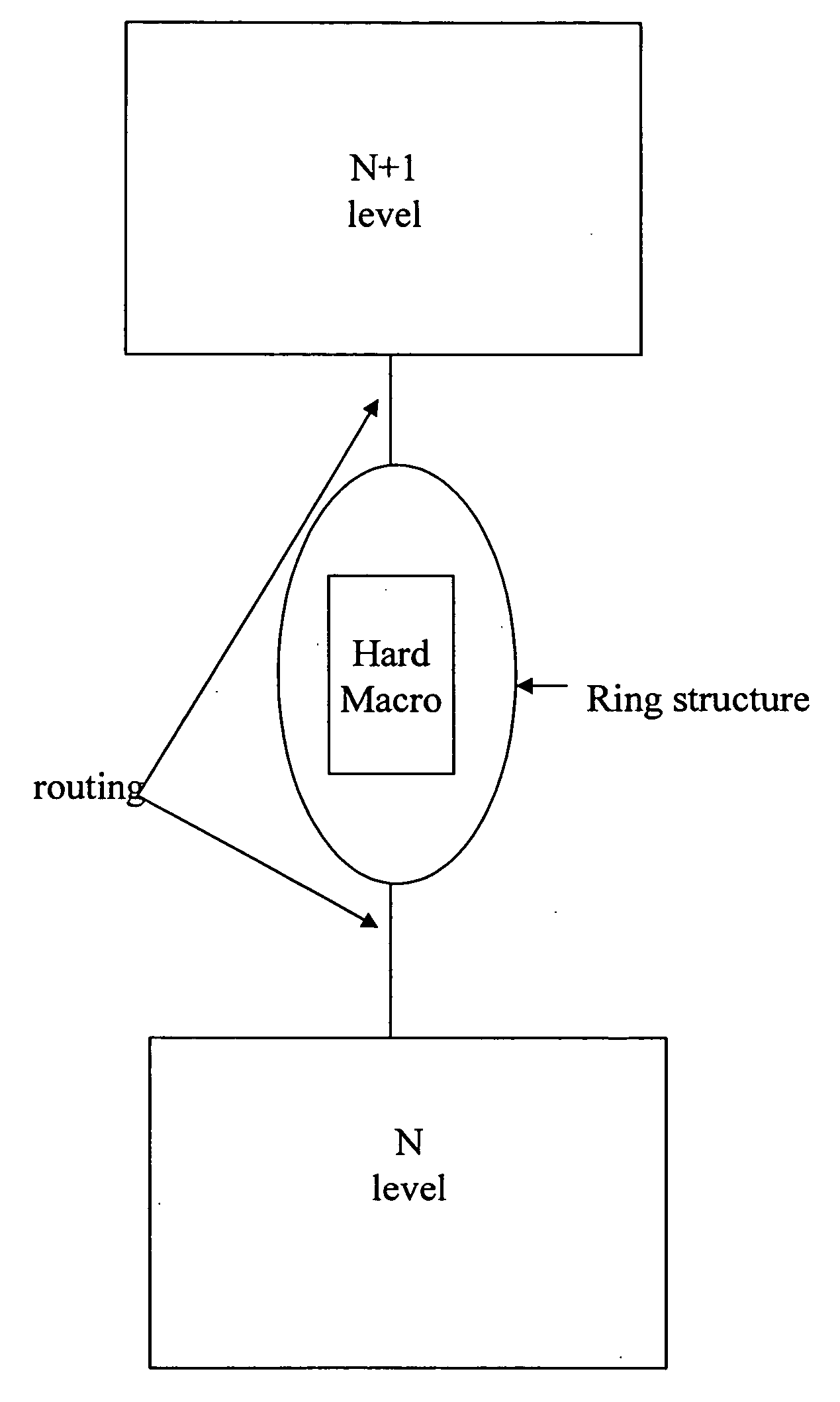
[0007] In a first aspect of the invention, a method comprises routing a power pattern from a reusable macro of a lower level upwards towards an upper level, n+1. The method further comprises extending the power pattern to a power structure on the upper level, n+1. The power structure may be at least a power grid. The method further comprises copying the power pattern for similar reusable macros of the reusable macro, thereby eliminating a need to route each individual instantiation of the similar reusable macros independently.
[0013] copy the power pattern for similar reusable macros of the reusable macro, thereby eliminating a need to route each individual instantiation of the similar reusable macros independently.

Problems solved by technology

Traditionally, though, the cost of RLM re-use is paid in additional area because of limitations in power routing these pseudo-regular structures.
In an example of the on-grid wiring approach, power patterns that are generated using a traditional top-down power routing do not recognize the logical similarities in underlying structures.
When a composite view of the m2 blockage for RLM “X” is generated, the net result is that channels five and six are blocked and therefore not available for signal wiring since only common non-blocked tracks can be used by the signal router.
This problem occurs on each level of metal over the RLM where it is necessary to create both power and signal routes.
This tends to force tradeoffs in terms of achieving maximum area utilization due to the relatively coarse nature of the power grid versus maintaining the flexibility to accommodate logic changes that grow the RLM.

Method used


Image

  • System and method to power route hierarchical designs that employ macro reuse
  • System and method to power route hierarchical designs that employ macro reuse
  • System and method to power route hierarchical designs that employ macro reuse

Examples


Embodiment Construction

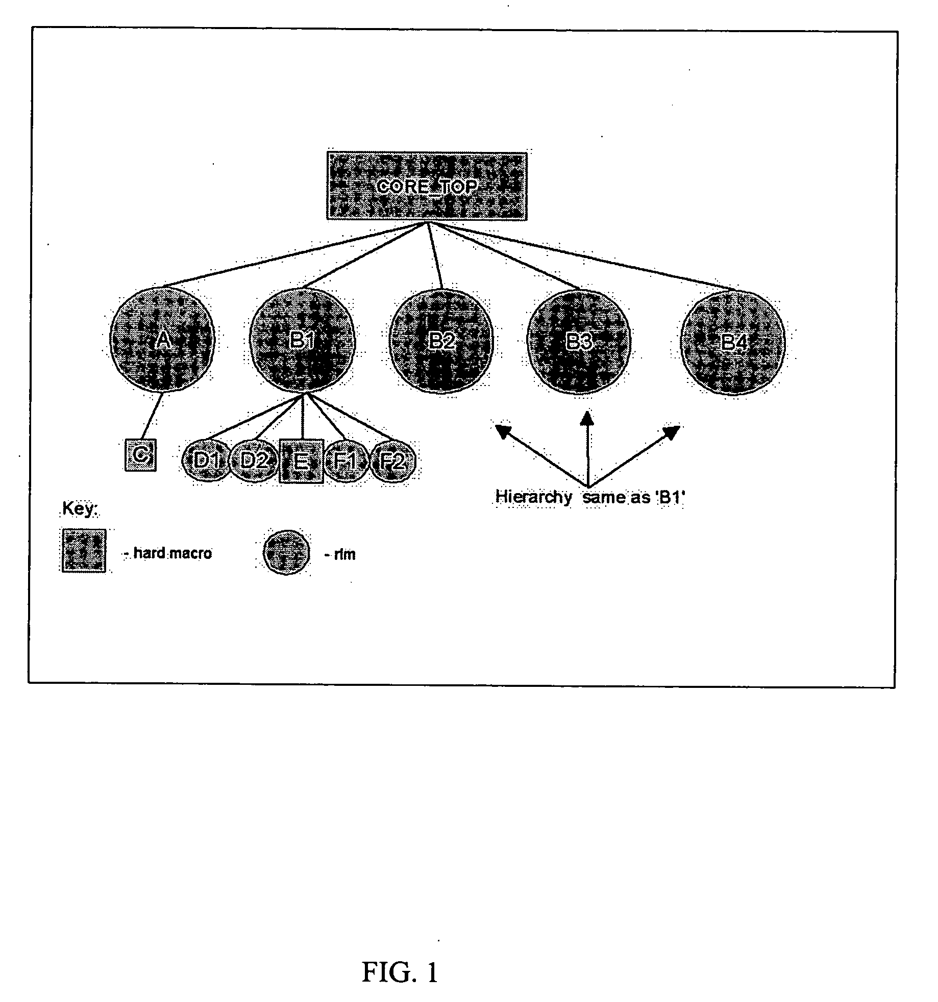
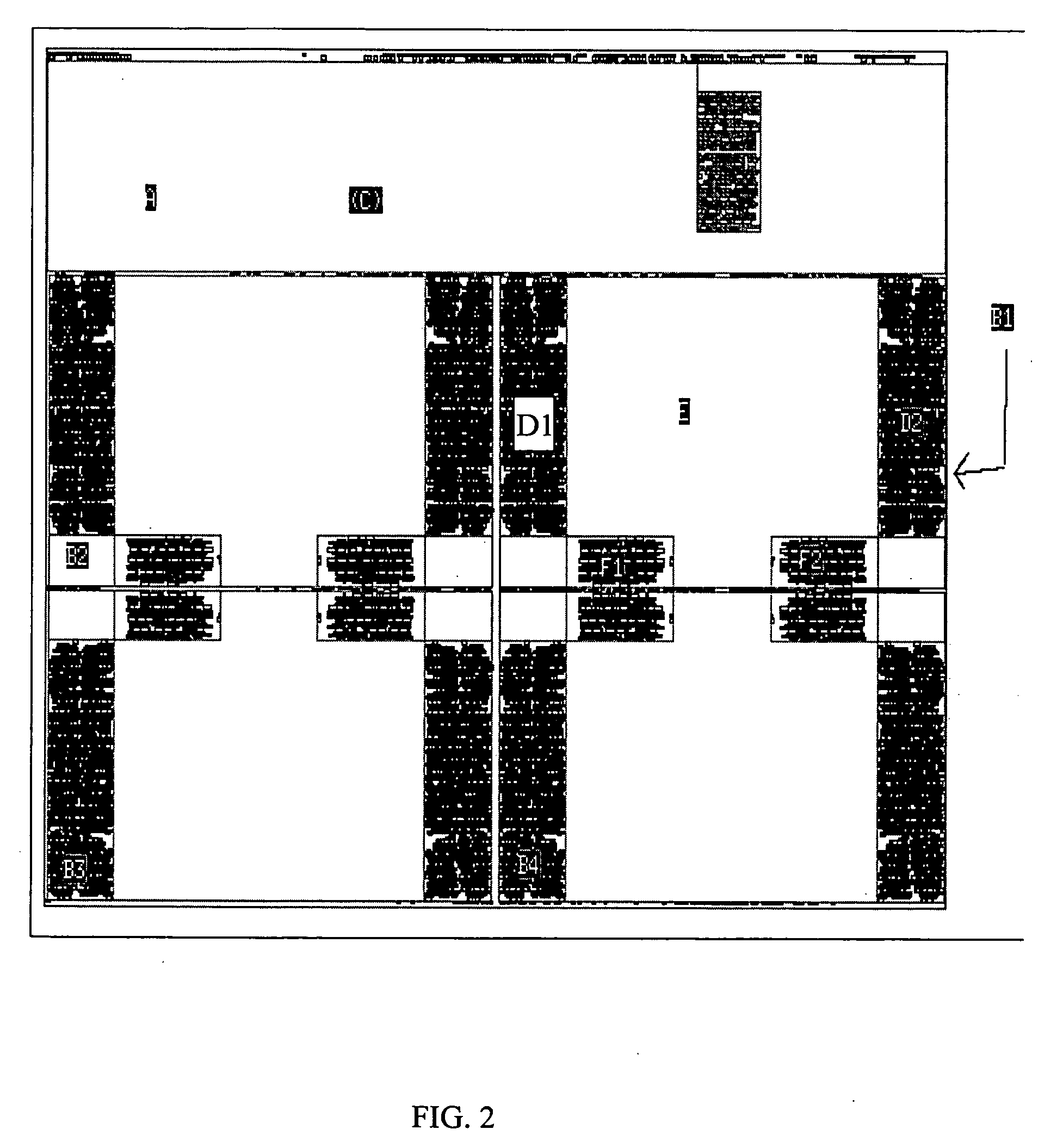
[0025] The invention relates to method of fabricating a circuit, and more particularly to a system and method to power route hierarchical designs that employ macro reuse. By using the method of the invention, routing of random logic macros (RLM) that are used multiple times in a hierarchical VLSI (very large scale integration) design can be achieved without having to route each individual instantiation independently. In embodiments of the invention, once an RLM has been routed and timed it can be copied and reused in a physical design, as is, and does not require any wiring changes. The method of the invention conserves valuable area, improves wireability, and reduces the time required for routing and timing each RLM instance. In this manner, the invention provides improved constraint resolution. Furthermore, by implementing the invention, each RLM possesses the same timing and power characteristics, which improves overall circuit performance.

[0026] As discussed in further detail b...


PUM


Abstract

A method of routing a random logic macro (RLM) that is used multiple times in a hierarchical VLSI design without having to route each individual instantiation independently. Once an RLM has been routed and timed it can be copied and reused in a physical design as is, and does not require any wiring changes. This method is an advantage over existing art because it conserves area, improves wireability, and reduces the time required for routing and timing each RLM instance. Furthermore, each RLM possesses the same timing and power characteristics, which improves overall circuit performance.

Description

FIELD OF THE INVENTION [0001] The invention relates to circuit fabrication, and more particularly to a system and method to power route hierarchical designs that employ macro reuse. BACKGROUND DESCRIPTION [0002] The repetitive use of the same subset of logic is a technique that can improve the efficiency of the physical design process in terms of area and the effort required to layout a design. The biggest advantage of the repetitive use (re-use) of the same subset of logic offers the capability to have each copy of this logic implemented with identical placement, wiring and timing. This result can be achieved on “n” number of random logic macros (RLM) at the reduced expense of placing, routing and timing only one copy of the design. For example, using this approach, only one of each type of RLM needs to have the internal logic placed, routed and timed. Traditionally, though, the cost of RLM re-use is paid in additional area because of limitations in power routing these pseudo-regul...

Claims


Application Information

Patent Timeline
IPC IPC(8): G06F17/50
CPCG06F17/5077G06F30/394
Inventor CORYER, GARYHAFER, DENNIS J.HYRISK, PAULLEPSIC, THOMAS M.
Owner IBM CORP
Learn More