Method and apparatus for routing an integrated circuit

a technology of integrated circuits and routing methods, applied in the field of integrated circuit routing techniques, can solve the problems of inaccurate timing violations, increased complexity of corresponding ic designs, and inability to accurately report congestion in top-level channels or within physical partitions, etc., and achieve the effect of facilitating early detection of congestion

Active Publication Date: 2006-12-28
SYNOPSYS INC
View PDF3 Cites 19 Cited by
  • Summary
  • Abstract
  • Description
  • Claims
  • Application Information

AI Technical Summary

Benefits of technology

[0015] One embodiment of the present invention provides a system that routes nets within an integrated circuit. During operation, the system receives a representation for the integrated circuit, which includes block boundaries for physical partitions of the integrated circuit generated from a hierarchical design placement of the integrated circuit. The system then classifies each net in the integrated circuit based on the location of pins associated with the net. (Note that pins are locations where the net is coupled to leaf-level circuit elements) Next, the system genera...

Problems solved by technology

As integrated circuit (IC) designers incorporate more system components onto a single IC chip, the complexity of the corresponding IC designs increases.
Unfortunately, traditional global routing techniques do not report congestion in top-level channels or within physical partitions accurately because they do not understand physical partition boundaries during the initial hierarchical design stage.
Furthermore, since pin locations are typically not finalized until later in the design cycle, a poor choice of pin location later in the design cycle can result in long inter-block wires that can cause timing violations which may not be detected until these blocks are finalized.
Since this new net uses the top-level channel, it may occupy a routing channel...

Method used


Image

  • Method and apparatus for routing an integrated circuit
  • Method and apparatus for routing an integrated circuit
  • Method and apparatus for routing an integrated circuit

Examples


Embodiment Construction

[0039] The following description is presented to enable any person skilled in the art to make and use the invention, and is provided in the context of a particular application and its requirements. Various modifications to the disclosed embodiments will be readily apparent to those skilled in the art, and the general principles defined herein may be applied to other embodiments and applications without departing from the spirit and scope of the present invention. Thus, the present invention is not limited to the embodiments shown, but is to be accorded the widest scope consistent with the principles and features disclosed herein.

Physical-Hierarchy-Aware Design Flow

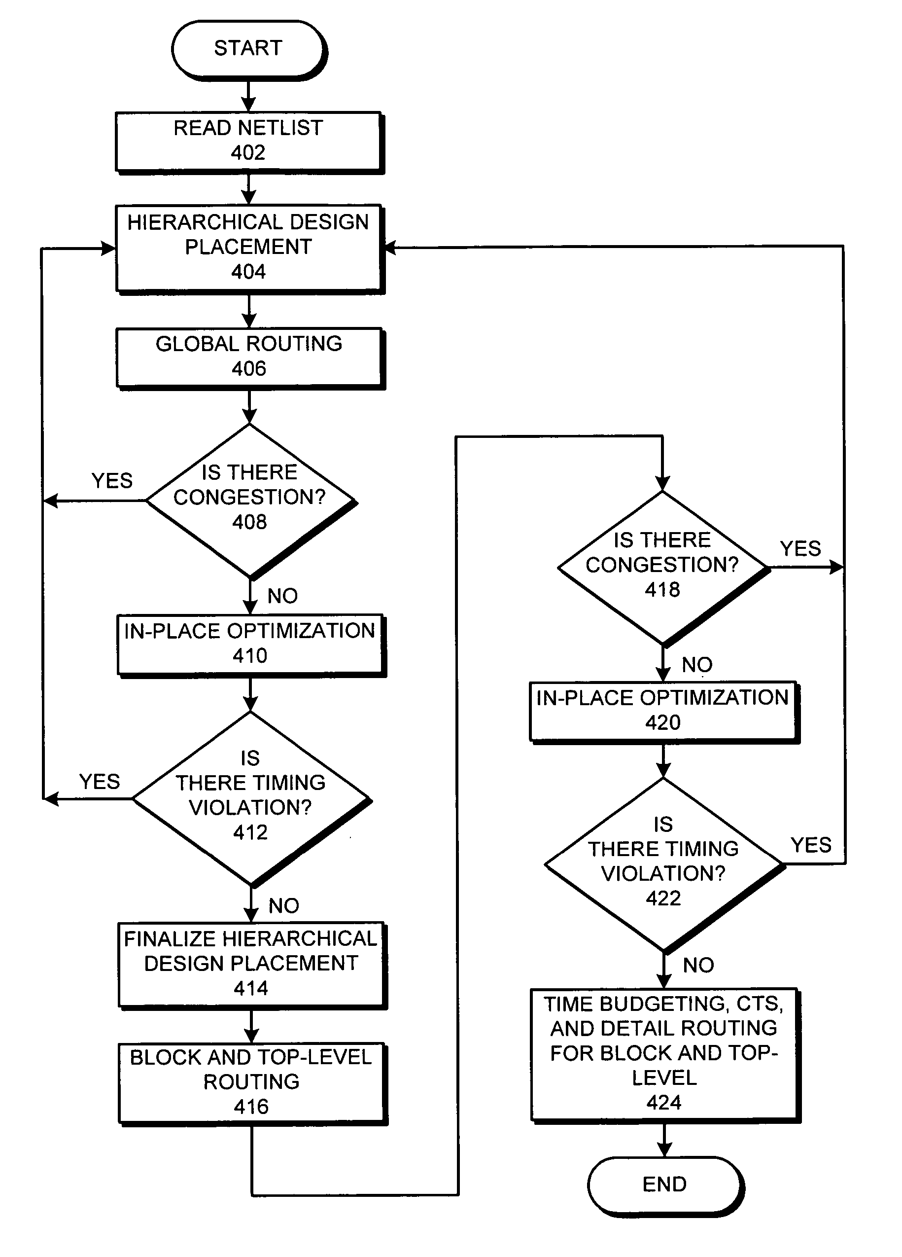
[0040]FIG. 3 presents a flow chart illustrating an typical hierarchical design process. The process begins when an IC designer writes register-transfer-level (RTL) code describing the function performed by an IC chip (step 302). Next, the IC designer performs synthesis on the RTL code to generate gates (step 304). The I...


PUM


Abstract

A system that routes nets within an integrated circuit. During operation, the system receives a representation for the integrated circuit, which includes block boundaries for physical partitions of the IC generated from a hierarchical design placement of the integrated circuit. The system then classifies each net in the integrated circuit based on the location of pins associated with the net. Next, the system generates routing constraints for each net based on the classification of the net and applies a feedthrough constraint to the physical partitions to restrict nets from feeding through physical partition boundaries. Finally, the system routes each net using the routing constraints for the net and the feedthrough constraints for the physical partitions. This routing is performed based on these block boundaries prior to finalizing the hierarchical design placement, thereby facilitating early detection of congestion or timing violations which can be corrected early in the design process.

Description

BACKGROUND [0001] 1. Field of the Invention [0002] The present invention relates to techniques for routing an integrated circuit. More specifically, the present invention relates to a physical partition-aware routing technique for routing signal lines through an integrated circuit. [0003] 2. Related Art [0004] Advances in semiconductor technology presently make it possible to integrate large-scale systems, including tens of millions of transistors, onto a single semiconductor chip. Integrating such large-scale systems onto a single semiconductor chip increases the speed at which such systems can operate, because signals between system components do not have to cross chip boundaries, and are not subject to lengthy chip-to-chip propagation delays. Moreover, integrating large-scale systems onto a single semiconductor chip significantly reduces production costs, because fewer semiconductor chips are required to perform a given computational task. [0005] As integrated circuit (IC) design...

Claims


Application Information

Patent Timeline
IPC IPC(8): G06F17/50
CPCG06F17/5077G06F30/394
Inventor KAUL, NEERAJRASHINGKAR, BALKRISHNATSENG, ANTHONY Y.TSENG, WEI-CHIH
Owner SYNOPSYS INC
Why Eureka
Try Eureka