Multidirectional heat dissipating structure

Inactive Publication Date: 2007-11-08
WEI WEN CHEN
View PDF12 Cites 16 Cited by
  • Summary
  • Abstract
  • Description
  • Claims
  • Application Information

AI Technical Summary

Benefits of technology

[0005] Hence, in light of the shortcomings in structural design of the aforementioned prior art heat dissipating device, the inventor of the present invention attentively researched various methods to resolve such drawbacks and design an heat dissipating device having good heat dissipation effectiveness in the limited volume of space within a host computer, which, following continuous research and improvements, culminated in the design of a multidirectional heat dissipating structure. Stated more specifically, the present invention uses stamping technology to stamp single heat dissipating strips and form heat dissipating fins that can be mutually joined and arranged in row form. The heat dissipating fins are further formed in different lengths, which can be arranged and assembled to form a plurality of flow guiding plates, each of which assumes a certain angle in accordance with the direction of air from a fan, thereby forming an appropriate converging air channel that smoothly guides the direction of air flow from a fan when running, causing cool air to rapidly flow towards heat conduction areas formed by spacings between the heat dissipating fins, thereby accelerating dissipation of heat from a heat source at a bottom portion of the heat dissipating fi

Problems solved by technology

Although cost of such a heat dissipating device is low, however, speed of heat conduction is relatively slow, and is only suitable for use in computers operating at relatively low speeds.
Hence, the heat dissipating effect of prior art heat dissipating devices is limited when used to dissipate heat from heating electronic components that are required to operate at high speed or for long periods of time.
Hence, simply replying on the heat dissipating fins is unideal and insufficient to satisfy heat dissipation requirements.
However, because of the perpendicul

Method used


Image

  • Multidirectional heat dissipating structure
  • Multidirectional heat dissipating structure
  • Multidirectional heat dissipating structure

Examples


Example

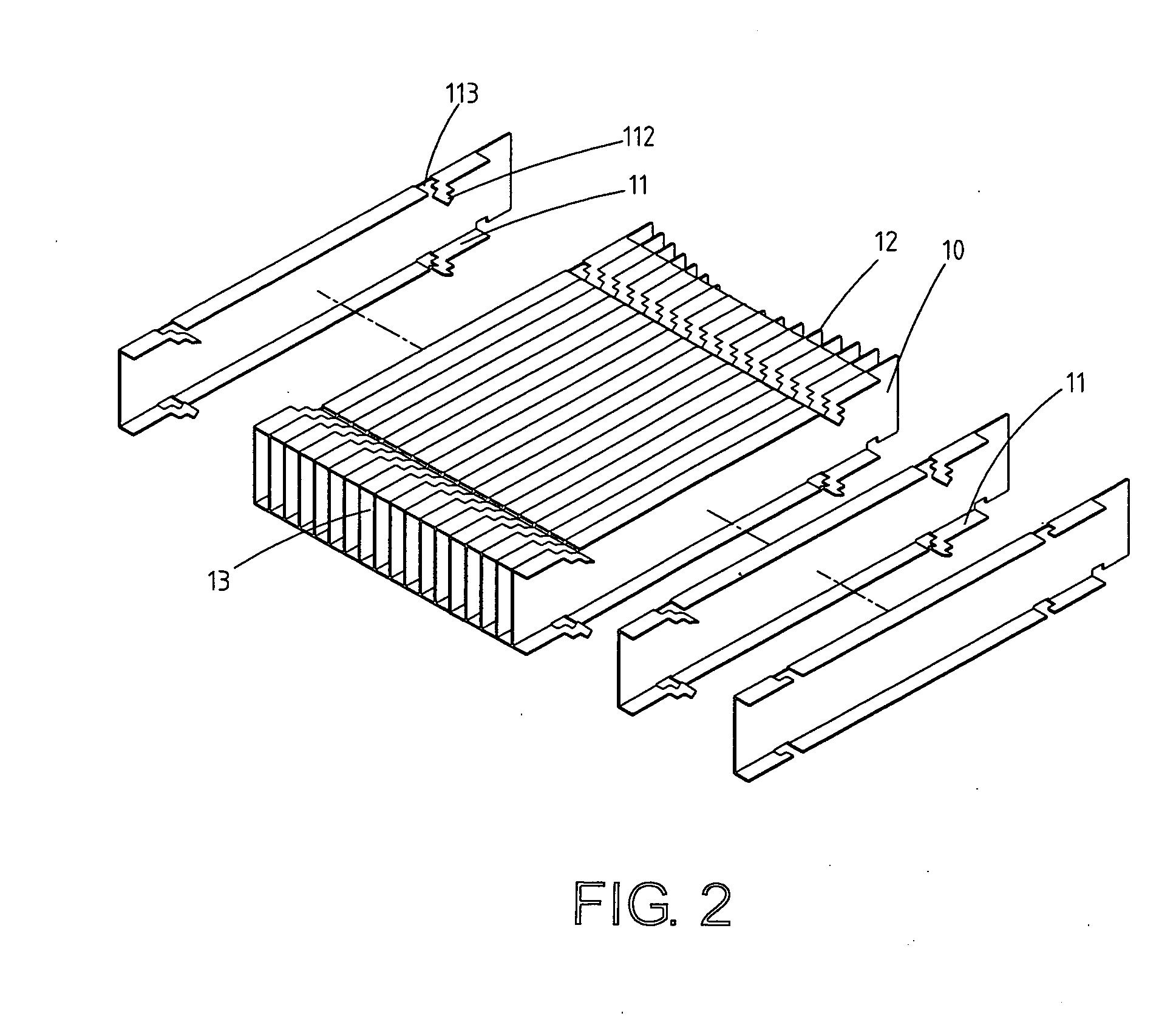
[0016] Referring to FIG. 2, which shows an exploded three-dimensional structural view of a preferred embodiment of a multidirectional heat dissipating structure of the present invention, wherein:

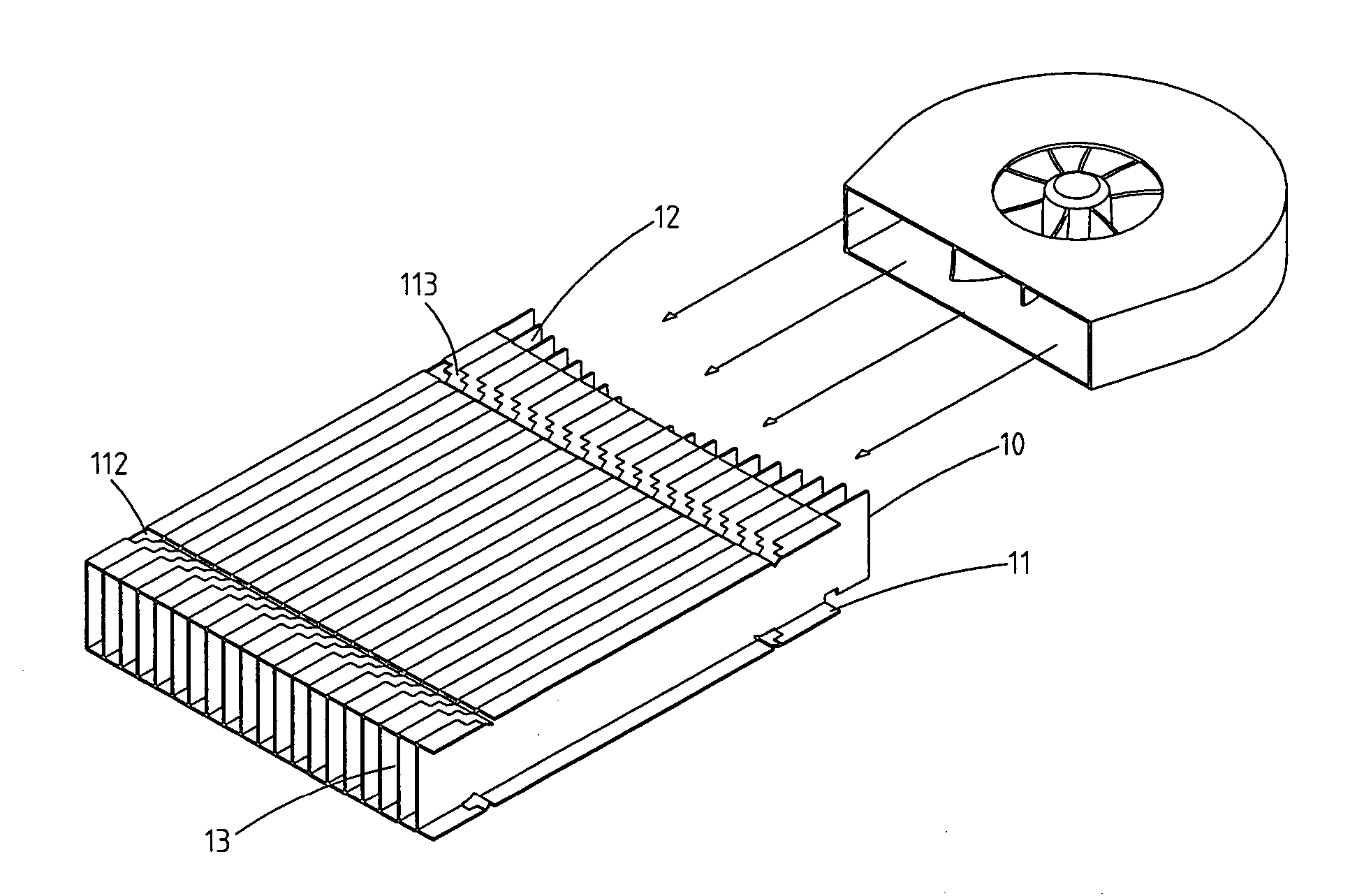
[0017] Heat dissipating fins (10) are molded laminate long strips, top and bottom end edges of each of which are horizontally bent to from heat conduction wing fins (11) thereat. Clasp slots (113) are formed on each of the heat conduction wing fins (11), and clasp hooks (112) respectively extend in the same direction from the clasp slots (113). A bend in each of the clasp hooks (112) forms an inverted fastener, which enable assembly of the corresponding front and back heat dissipating fins (10) therewith, thereby allowing a set of the heat dissipating fins (10) to be assembled one strip at a time without resulting in the heat dissipating fins (10) arbitrarily coming apart. The present invention is primarily characterized in that when stamping, an end of each of the heat dissipating fins (10...


PUM


Abstract

A multidirectional heat dissipating structure that joins and assembles a plurality of heat dissipating fins, length of each of which vary, and can be arranged and assembled to form a plurality of flow guiding plates, each of which assumes a certain angle in accordance with the direction of air, thereby forming an appropriate air channel that smoothly guides an air flow from a fan, causing cool air to rapidly flow towards heat conduction areas formed by spacings between the heat dissipating fins, thereby accelerating dissipation of heat from a heat source at a bottom portion of the heat dissipating fins. Moreover, the heat dissipating structure is applicable for use in various horizontal blowing and downward blowing heat dissipating devices.

Description

BACKGROUND OF THE INVENTION [0001] (a) Field of the Invention [0002] The present invention relates to a multidirectional heat dissipating structure, and more particularly to a heat dissipating structure that uses heat dissipating fins of different length assembled to structure flow guiding plates that form an air channel of certain angle, which enables cool air to follow the air channel and be rapidly guided into the heat dissipating fins to dissipate hot air and effectively reduce temperature. [0003] (b) Description of the Prior Art [0004] Accordingly, in order to resolve the problem of overheating of components within a host computer, in general, a heat dissipating device is installed on top of the heating electronic components, which is able to dissipate heat energy from the high temperature produced by the electronic components. Moreover, heat dissipating fins of a prior art heat dissipating device are disposed on a bottom plate of a heat sink, and the bottom plate is placed in ...

Claims


Application Information

Patent Timeline
IPC IPC(8): H05K7/20
CPCF28F3/02H01L23/3672H01L23/467H01L2924/0002H01L2924/00
Inventor WEI, WEN-CHEN
Owner WEI WEN CHEN
Why Eureka
Try Eureka