Radiometric Calibration

a radiometer and calibration technology, applied in the field of radiometric calibration, can solve the problems of difficult to realise a dicke radiometer, low sensitivity of the switched system, and the effect of the antenna or other components before the switch cannot be calibrated out, and achieve good image quality

Inactive Publication Date: 2007-11-08
THE UNIV COURT OF THE UNIV OF GLASGOW
View PDF12 Cites 16 Cited by
  • Summary
  • Abstract
  • Description
  • Claims
  • Application Information

AI Technical Summary

Benefits of technology

[0019] The imaging apparatus may be operable to cause the scanner to scan across the junction between the hot and cold loads during each sweep of the target area so that calibration is done on a line-by-line basis.
[0020] In scanned images, it is important that successive scans align well with each other, i.e. are in registration with each other. Due to mechanical backlash or electronic phase shifts in the detection electronics, successive scans may be slightly misaligned. This must be corrected to ensure good image quality. The junction between adjacent hot and cold calibration loads creates a thermal step. Scanning across this thermal step provides a well-defined reference feature against which each line scan can be adjusted to ensure correct registration. To take advantage of this, the imaging apparatus may comprise means for detecting scanning registration errors for each sweep of the imager using the calibration load image data and means for correcting the target image data depending on any detected registration errors.

Problems solved by technology

A problem with this, however, is that switching to the calibration reference takes place after the antenna in the signal chain and so any effects of the antenna, or other components before the switch, cannot be calibrated out.
In addition, such switched systems have a relatively low sensitivity.
Furthermore, at millimetre wave frequencies it is difficult to realise a Dicke radiometer due to the lack of available low-loss switches.
However, this is not easy to achieve and in practice highly absorbing materials are often quite reflective due to a high refractive index.
However, loads made of tall thin wedges or pyramids suffer from the practical problem of being difficult to manufacture.
However, these materials are often foams loaded with lossy material, and as such are not suitable for use in a calibration load whose temperature is to be controlled by thermal conduction through the load material.

Method used


Image

  • Radiometric Calibration
  • Radiometric Calibration
  • Radiometric Calibration

Examples


Embodiment Construction

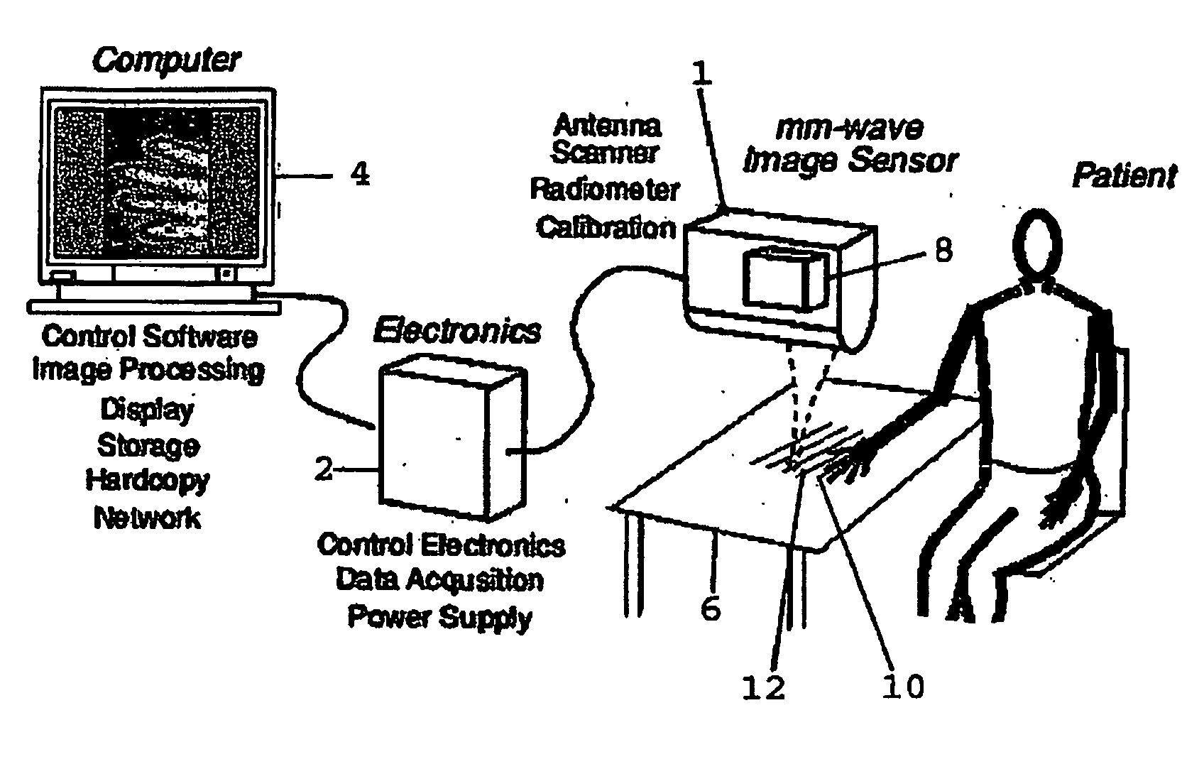
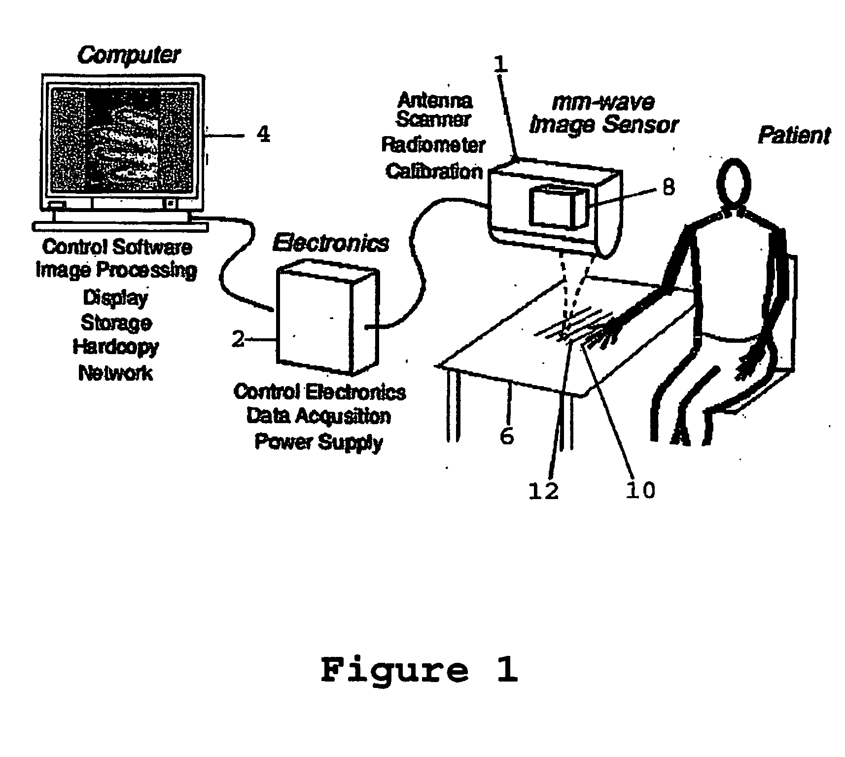
[0040]FIG. 1 shows an example of a passive non-contacting imager 1 that is operable to detect millimetre wavelength radiation emitted from the body. By passive it is meant that no radiation is directed onto the patient by the imager. Instead the imager is operable to detect radiation that is naturally emitted from the patient's body. By non-contacting it is meant that the imager does not physically contact the patient. The imager of FIGS. 1 and 2 is ideally operable to form an image from emitted radiation in the frequency range of 10-200 GHz, and preferably in the range 90-100 GHz. This imager is the subject of a co-pending International patent application PCT / GB2003 / 001284, the contents of which are expressly incorporated herein by reference.

[0041] The imager of FIG. 1 is connected to electronic circuitry 2 for controlling and supplying electrical power thereto and also receiving image data therefrom. Received data is processed and displayed as an image on a computer 4. The imager...


PUM


Abstract

A calibration load is provided for calibrating a signal in a range of wavelengths or of a single known wavelength. In one embodiment, the load comprises a calibration surface including an emissive material, the calibration surface having relief features, such as pyramids or wedges, that have a dimension that is substantially the same as or less than the shortest wavelength of the range of wavelengths or the single known wavelength that has to be calibrated.

Description

[0001] The present invention relates to the calibration of microwave radiometers and in particular radiometric imaging instruments. BACKGROUND OF THE INVENTION [0002] It is well known that microwave radiometers, such as Dicke or noise injection or total power radiometers, require regular calibration of their thermal response in order to correct for drift and fluctuations. When radiometers are used in imaging systems, where sensitivity fluctuations can manifest themselves as unwanted stripes or patterns in the image, regular calibration is particularly important to avoid degradation of the image. [0003] Thermal calibration of radiometers can be done in various different ways. For example, in the Dicke radiometer or noise injection radiometer (NIR), the receiver is rapidly switched between the target and a calibration reference. A problem with this, however, is that switching to the calibration reference takes place after the antenna in the signal chain and so any effects of the anten...

Claims


Application Information

Patent Timeline
Patent Type & Authority Applications(United States)
IPC IPC(8): G01D18/00G01J5/52
CPCG01J5/522G01K15/00G01K11/006G01J5/53
Inventor ROBERTSON, DUNCAN ALEXANDERMACFARLANE, DAVID GRAHAMLESURF, JAMES CHRISTOPHER GEORGE
Owner THE UNIV COURT OF THE UNIV OF GLASGOW
Why Eureka
Try Eureka