System and method for reducing the chance of fires and/or explosions

a technology of electrical arc and fire, applied in the direction of electrical devices, anti-theft devices, coupling device connections, etc., can solve the problems of not using the pressure of inert gas in the prior art system or method, not maintaining power to safety electrical equipment, and not using a single system or method. , to achieve the effect of increasing the force, and reducing the possibility of fire starting

Inactive Publication Date: 2007-11-08
GORS DONALD
View PDF26 Cites 21 Cited by
  • Summary
  • Abstract
  • Description
  • Claims
  • Application Information

AI Technical Summary

Benefits of technology

[0012] Still another object of the present invention is to provide a system that uniformly distributes ejection force from the first portion to the second portion. A feature of the system is two conduits that are joined and tightly sealed to the first portion, the two conduits being disposed adjacent to corresponding outer recesses in the first portion. Another feature of the system is that the outer recesses are disposed on opposing sides of the recessed electrical receptacle and are configured to snugly receive cooperating plugging fingers of the second portion. An advantage of the system is that ejection force is symmetrically applied to the second portion on opposite sides of the electrically conductive rod which snugly inserts into the recessed electrical receptacle in the first portion thereby completely separating the second portion from the first portion when the vehicle impacts an object.
[0013] Another object of the present invention is to provide a system capable of completely separating the first and second portions of the cable connector when the plugging fingers are snugly inserted into the outer recesses, and when the electrically conductive rod is snugly inserted into the recessed receptacle. A feature of the system is outer recesses with diameters relatively larger than the diameters of the conduits supplying inert gas thereto. Another feature of the system is concave or arcuate end walls of the plugging fingers that form a gap between an inner wall of the outer recesses and the plugging fingers. An advantage of the system is that increased force can be applied to the concave end walls of the plugging fingers to completely eject the second portion from the first portion thereby de-energizing the second portion and all electrical components connected thereto when the vehicle impacts an object. Another advantage of the system is that inert gas is allowed to flow from the first portion unrestricted by the second portion thereby blanketing the adjacent area more quickly and reducing the possibility of a fire starting.
[0014] Another object of the present invention is to provide a system that prevents conductive wires in the first and second portions from being pulled from or otherwise damaging the first and / or second portions as the first and second portions are forcibly joined or forcibly separated. A feature of the system is an enlarged end portion of the conductive wire in the first portion. Another feature of the system is an enlarged electrically conductive coupling disposed in the second portion, the coupling having a first end joined to the rod and a second end joined to the conductive wire. An advantage of the system is that the enlarged end portion of the wire and the enlarged coupling form retaining ridges that maintain the positions of the wires in the first and second portions irrespective of the joining or separation forces applied to the first and second portions.
[0015] Briefly, the invention provides a system for reducing the chance of fire and / or explosion when a vehicle impacts an object comprising a cable connector having first and second portions that separate when predetermined conditions are satisfied; a pressurized container of inert gas that promotes the separation of said first and second portions of said cable connector, said first portion being connected to the ungrounded terminal of a battery in the vehicle; means for sensing impact between the vehicle and the object, means for extinguishing an electrical arc in said first portion of said cable connector during separation of said first and second portions; and means for initiating inert gas flow from said pressurized container to said cable connector whereby said first and second portions of said cable connector are separated a distance sufficient to interrupt electrical current, said inert gas flow continuing until said container supplying said inert gas depressurizes thereby reducing the possibility of fire and / or explosion by blanketing the area adjacent to said first portion of said cable connector with inert gas.
[0016] The invention further provides a system for disconnecting an electrical power source in a moving vehicle when the moving vehicle is involved in a collision with an object comprising a cable connector having first and second portions that separate when predetermined conditions are satisfied, said first portion being connected to the ungrounded terminal of an electrical power source; means for sensing a predetermined magnitude of impact of a moving vehicle with an object; and means for initiating inert gas flow from an inert gas container to said first portion of said cable connector when a predetermined magnitude of impact is sensed whereby said first and second portions of said cable connector separate such that electrical arcs are extinguished and an adjacent area is blanketed with inert gas resulting in reducing the possibility of a fire and / or explosion that may occur when a moving vehicle is involved in a collision.
[0017] The invention also provides a method for reducing the possibility of fire and / or explosion when a vehicle is involved in a collision, said method comprising the steps of providing a cable connector having first and second members that are initially joined together, said first member being electrically connected to an ungrounded terminal of a battery; providing means for forcibly separating said first and second members; measuring the magnitude of force generated by a collision between a vehicle and an object; initiating the forcible separation of said first and second members when said measured magnitude of force reaches a predetermined magnitude; isolating an electrically energized portion of said first member to prevent electrical arcing after the automobile engages an object; and blanketing the region proximate said first member with inert gas whereby the possibility of fires and / or explosions are reduced in the event fuel engages a hot spot.

Problems solved by technology

Most of the prior art systems and methods do not maintain power to safety electrical equipment such as satellite monitoring systems that determine the location of a vehicle.
The problem with the prior art is that there are is no single system or method that both prevents electrical arcs and that blankets a predetermined area with inert gas to reduce the chance of fires and / or explosions.
Further, there is no prior art system or method that utilizes the pressure of the inert gas to force apart an electrical component to isolate an electrical power source to reduce the chance of fires and / or explosions.
Thus, there is no prior art method or system that prevents electrical arcs and that distributes inert gas via the same components.
When a vehicle impacts and object, components required to prevent or reduce the chance of fire can be damaged resulting in system failure and an automotive fire and / or explosion.
The more components utilized for fire prevention, the greater the possibility of system failure due to one or more of the components being damaged.
Further, the more components utilized for fire prevention, the longer the response time for the fire prevention system to react after vehicle impact.
A forceful vehicle impact of great magnitude may render a long response time thereby rendering the fire prevention system ineffective.

Method used


Image

  • System and method for reducing the chance of fires and/or explosions
  • System and method for reducing the chance of fires and/or explosions
  • System and method for reducing the chance of fires and/or explosions

Examples


Embodiment Construction

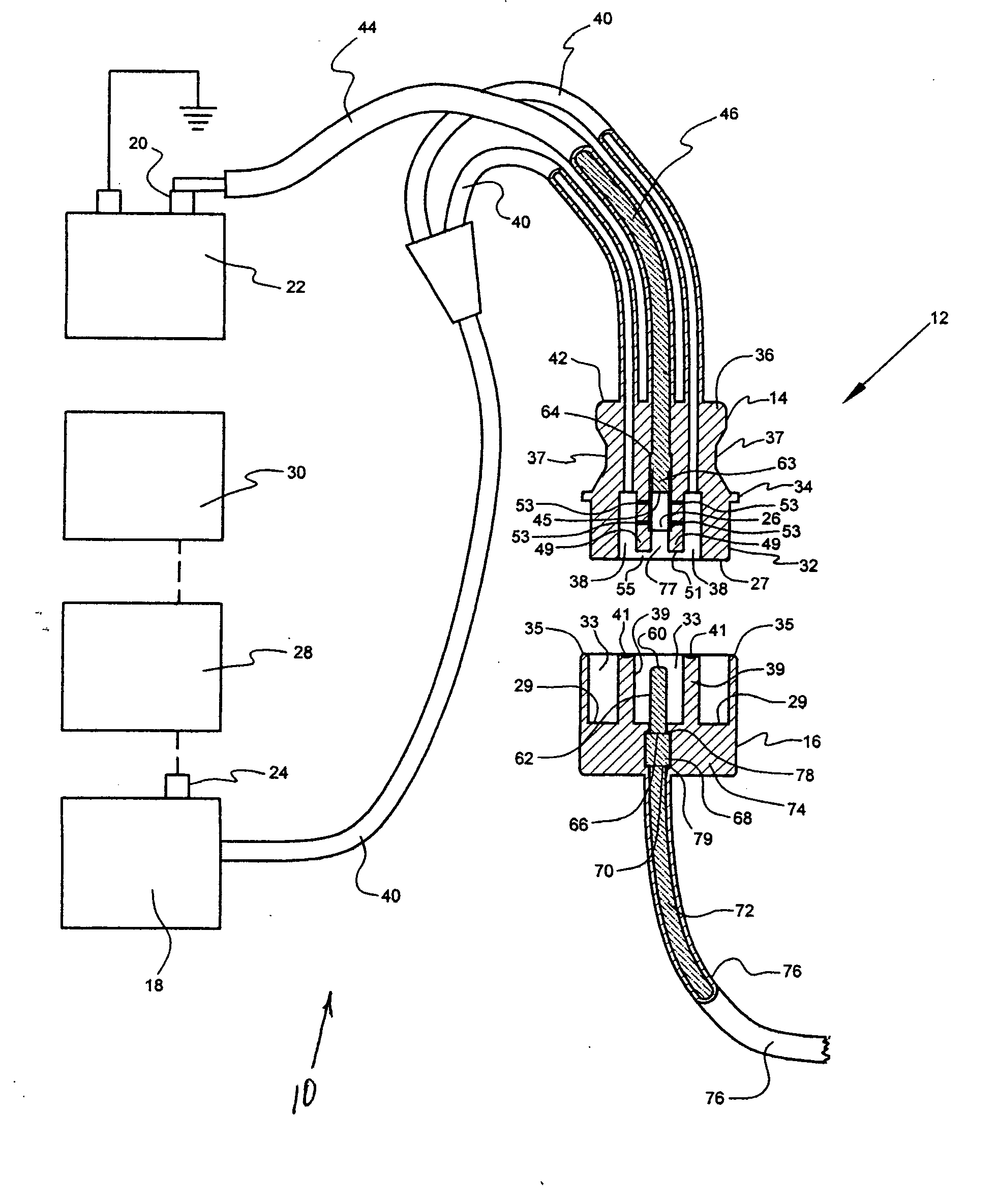
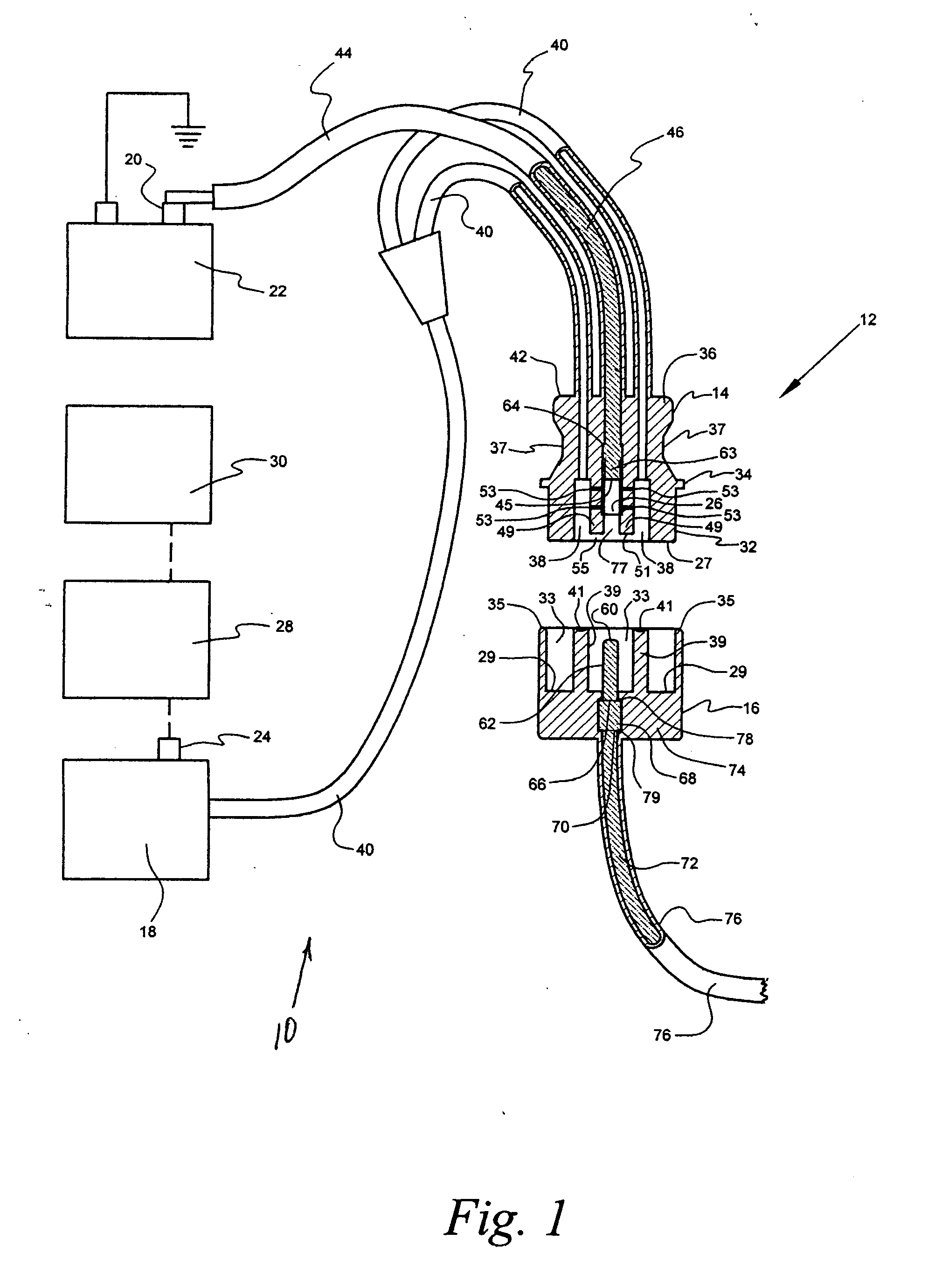
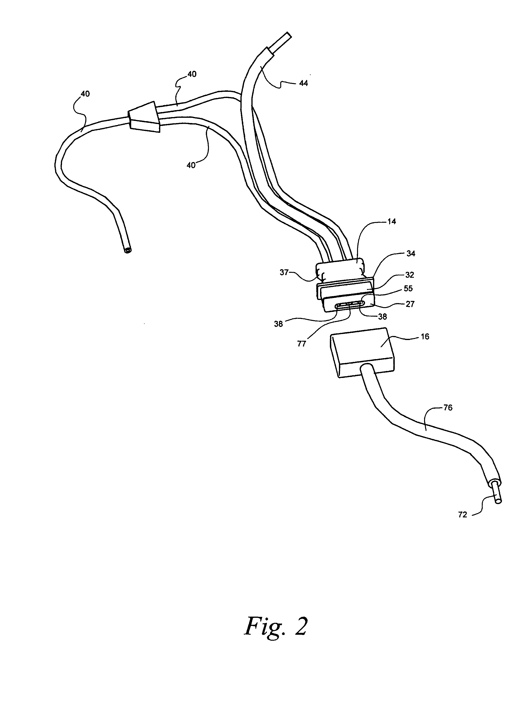
[0029] Referring now to the drawings, a system for reducing the possibility of fire and / or explosion when a vehicle impacts an object in accordance with the present invention is denoted as numeral 10. The system 10 includes a connector 12 having a first portion 14 connected to an ungrounded terminal 20 of a typical vehicle battery 22 or similar electrical power source for a vehicle (not depicted), and a second portion 16 connected to all vehicle electrical components requiring power from the power source 22; one or more inert gas canister 18 having an internal pressure that facilitates the separation of the first and second portions 14 and 16 of the connector 12 and that blankets an area adjacent to the connector 12 with inert gas when predetermined conditions are satisfied. The first portion 14 is connected to the ungrounded terminal 20 of a battery 22 in the vehicle.

[0030] The system 10 further includes electric squib means 24 for initiating pressurized inert gas flow from the ca...


PUM


Abstract

A system 10 and method for reducing the possibility of fires and/or explosions when a vehicle impacts an object includes a cable connector 12 having a first portion 14 connected to an ungrounded terminal 20 of a battery 22 in the vehicle and a second portion 16 connected to all vehicle electrical components requiring power from battery 22, an inert gas canister 18 having an internal pressure that facilitates the separation of the first and second portions 14 and 16 of the cable connector 12 when predetermined conditions are satisfied, electric squib means 24 for initiating pressurized inert gas flow from the canister 18 to the first portion 14 of the cable connector 12, an accelerometer 28 for sensing impact between the vehicle and the object, and a microprocessor 30 for signaling the accelerometer 28 to “fire” the squib means 24 when the magnitude of impact requires an inert gas flow to the first portion 14 whereby the second portion 16 is forcibly ejected from the first portion 14 and the area adjacent to the first portion 14 is blanketed with inert gas thereby reducing the possibility of fire and/or explosion resulting from fuel vapors engaging electrical arcs or vehicle “hot spots.”

Description

BACKGROUND OF THE INVENTION [0001] 1. Field of the Invention [0002] The present invention relates to a system and method for reducing the possibility of a fire started from an electrical arc, and more particularly, to a system and method for disconnecting a D.C. or A.C. power source from an electrical system or preselected electrical components of a vehicle while maintaining power to safety electrical components including the present invention, and at the same time blanketing the area adjacent to the battery with inert gas thereby reducing the chance of a fire and / or explosion. [0003] 2. Background of the Prior Art [0004] Systems and methods for reducing the possibility of fires and / or explosions started by electrical arcs resulting from moving vehicles impacting object including automobile accidents are well known. Generally, the systems and methods disconnect the power cable from the battery via springs, pyrotechnic propellant, relays and / or diodes among other components, to elect...

Claims


Application Information

Patent Timeline
Patent Type & Authority Applications(United States)
IPC IPC(8): B60L1/00
CPCB60R21/0132B60R21/0136Y10T403/1641B60R2021/01252B60R21/017
Inventor GORS, DONALD
Owner GORS DONALD
Why Eureka
Try Eureka