Magnetic flux-coupling type superconducting fault current limiter

a superconducting and current limiter technology, applied in the direction of superconducting magnets/coils, emergency protective arrangements for limiting excess voltage/current, etc., can solve the problem of placing a great load on the power system, and achieve the effect of limiting fault current, reducing load, and operating more rapidly

Inactive Publication Date: 2007-11-08
IND ACADEMIC CORP FOUND YONSEI UNIV
View PDF3 Cites 13 Cited by
  • Summary
  • Abstract
  • Description
  • Claims
  • Application Information

AI Technical Summary

Benefits of technology

[0015]The operational characteristics of the magnetic flux-coupling type superconducting fault current limiter are divided into an additive polarity winding, and a subtractive polarity winding depending on the directions between the primary and secondary coils. The inductance ratio between two the coils controls the value of the initial line current after a fault occurs.
[0016]According to the magnetic flux-coupling type superconducting fault current limiter of the present invention, when a fault occurs, the entire voltage is divided by the primary coil and the secondary coil to reduce the load on the superconducting element, and the limiter operates more rapidly than the conventional magnetic superconducting flux-lock type fault current limiter during a quench time, which is beneficial in limiting the fault current.

Problems solved by technology

If the magnetic flux-lock type superconducting fault current limiter is wound into an additive polarity winding and the inductance ratio between the primary coil and the secondary coil is set to 1, this places a great load on the power system.

Method used


Image

  • Magnetic flux-coupling type superconducting fault current limiter
  • Magnetic flux-coupling type superconducting fault current limiter
  • Magnetic flux-coupling type superconducting fault current limiter

Examples


Embodiment Construction

[0034]Reference will now be made in detail to the preferred embodiments of the present invention, examples of which are illustrated in the accompanying drawings.

[0035]Reference now should be made to the drawings, in which the same reference numerals are used throughout the different drawings to designate the same or similar components in the following description of the present invention, detailed descriptions may be omitted if it is determined that the detailed descriptions of related well-known functions and constructions may make the gist of the invention unclear.

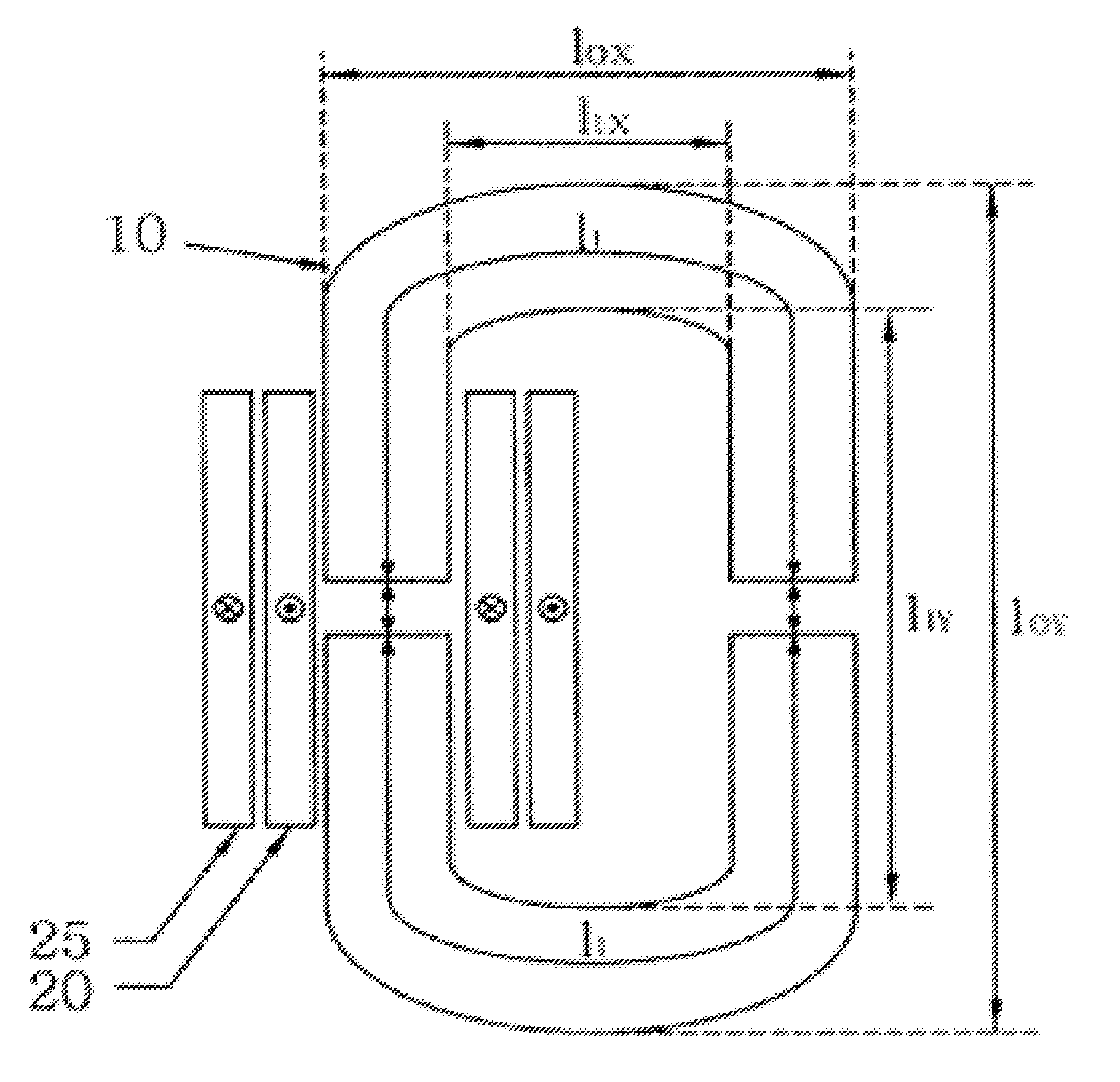
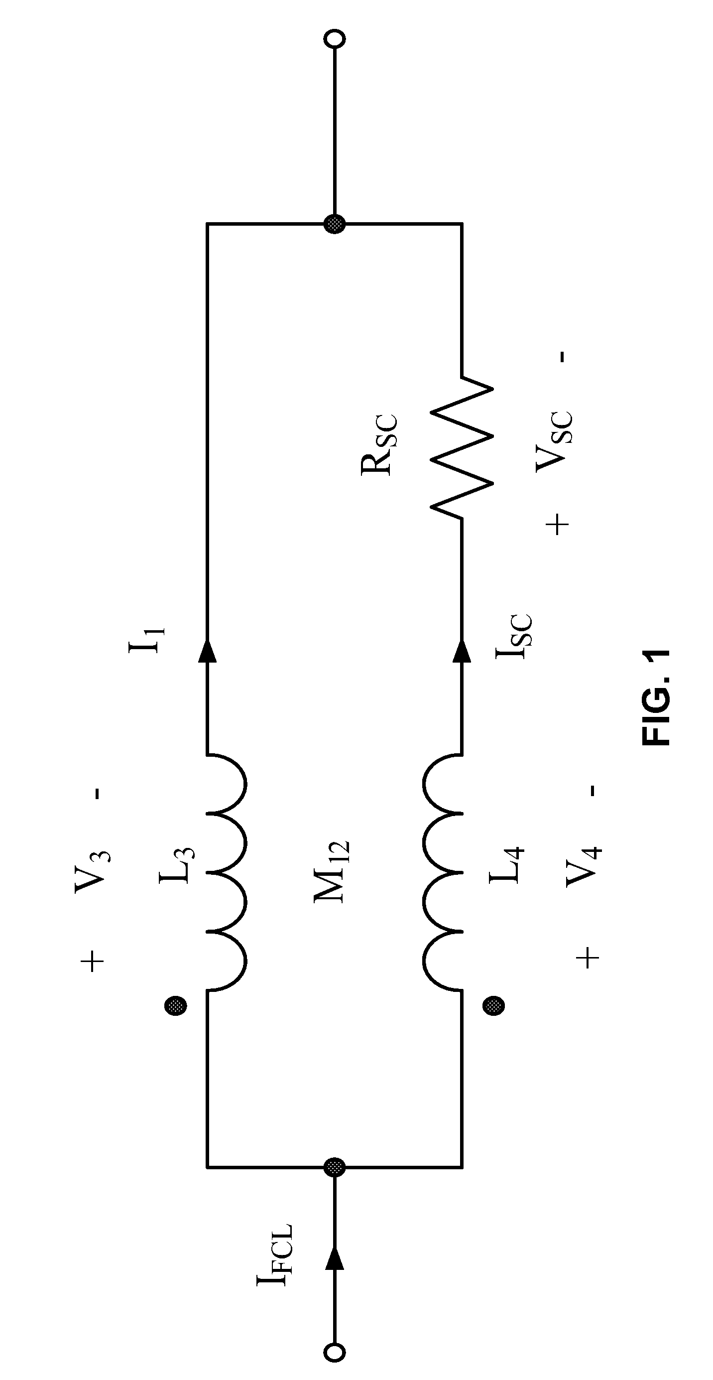
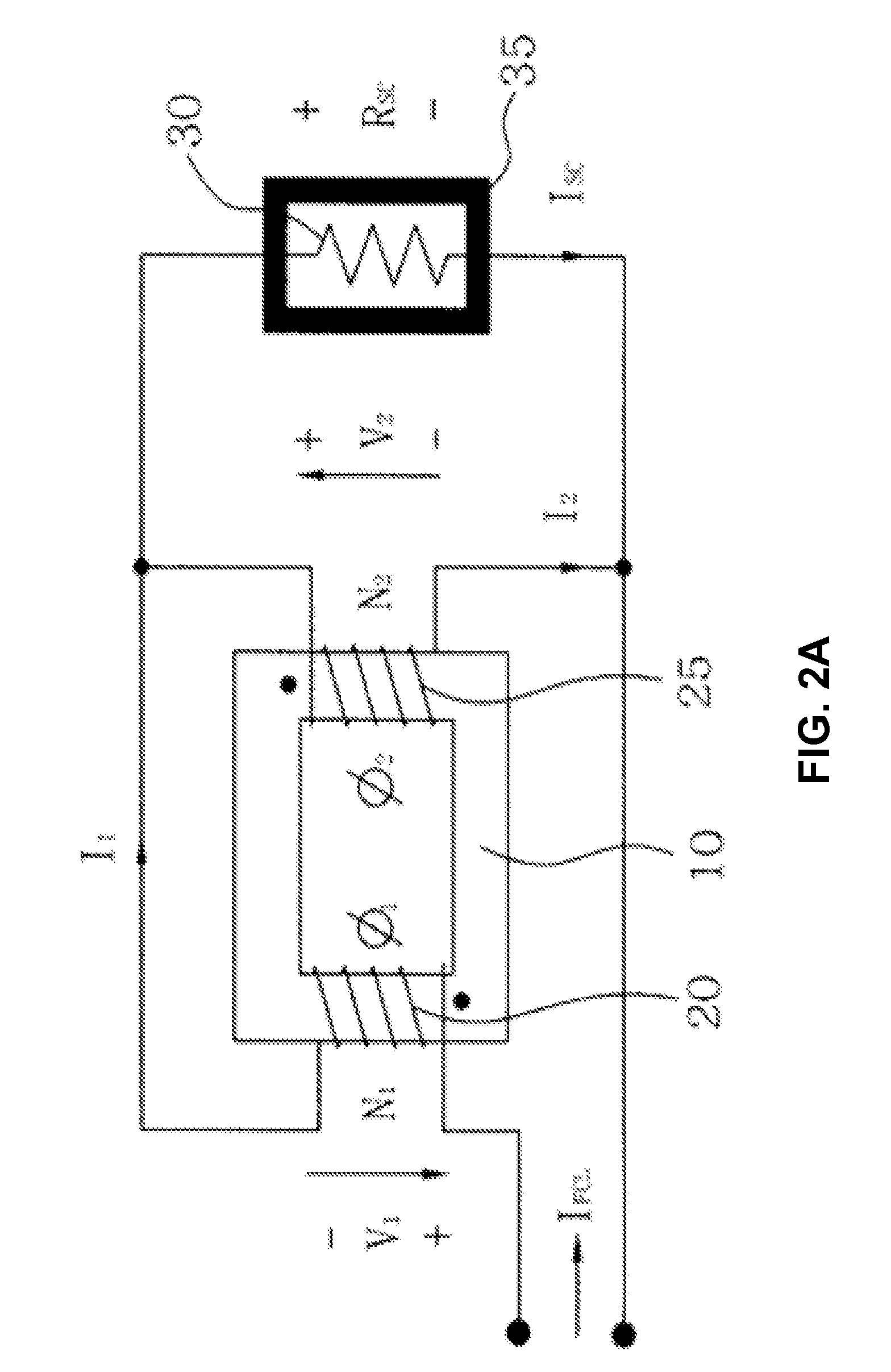
[0036]FIG. 2A is an equivalent circuit diagram of a magnetic flux-coupling type fault current limiter in accordance with one embodiment of the present invention, FIG. 2B is a circuit configuration for testing it and FIG. 2C is a cross-sectional view of a reactor.

[0037]In one embodiment of the invention, the magnetic flux-coupling type superconducting fault current limiter includes: a magnetic iron core (10), a primary co...


PUM

PropertyMeasurementUnit
voltagesaaaaaaaaaa
resistanceaaaaaaaaaa
currentaaaaaaaaaa

Abstract

A magnetic flux coupling-type superconducting current limiter is capable of protecting lines more effectively by winding reactors of a primary coil and a secondary coil in series in the structure where the primary coil and the secondary coils are wound in parallel in the conventional magnetic flux-lock type current limiter to increase a linked flux generated from an iron core. An electric conducting current which rapidly increases when a fault occurs is divided into the secondary coil and a superconducting coil to decrease a load on the superconducting element and it is opened more rapidly than the existing superconducting current limiter during a quench time such that it better limits a fault current.

Description

CROSS-REFERENCE TO RELATED APPLICATIONS[0001]The present application claims priority to Korean Patent Application No. 10-2006-0040270, filed May 4, 2006, which is incorporated herein by reference in its entirety.BACKGROUND OF THE INVENTION[0002]1. Field of the Invention[0003]The present invention relates, generally, to magnetic flux-coupling type superconducting fault current limiters, more particularly, to an environment-friendly and semi-permanent magnetic flux-coupling type superconducting fault current limiter that has a primary coil winding and a secondary coil of the magnetic flux-coupling superconducting fault current limiter in series and superconducting element winding around the secondary coil in parallel so as to reduce a load on a element when a fault occurs, and to improve the handling and the time for recovering a fault current using linked flux as much as possible.[0004]2. Description of the Related Art[0005]As the superconducting fault current limiter uses a quench c...

Claims


Application Information

Patent Timeline
Patent Type & Authority Applications(United States)
IPC IPC(8): H01F6/00
CPCH01F6/00H01F6/006Y02E40/69H01F2006/001H02H9/023H01F6/02Y02E40/60H02H9/02
Inventor CHOI, HYO-SANGPARK, HYOUNG-MINCHO, YONG-SUNNAM, GUENG-HYUNLEE, NA-YOUNGHAN, TAE-HEELIM, SUNG-HUNCHUNG, DONG-CHUL
Owner IND ACADEMIC CORP FOUND YONSEI UNIV
Why Eureka
Try Eureka