Optical sheet, method for producing the same and display apparatus

a technology of optical sheets and display apparatuses, applied in the field of optical sheets, can solve the problems of lowering the display affecting the performance affecting the quality of the display apparatus, so as to reduce the shrinkage ratio due to the curing of the hardening resin, the effect of lowering the strength of the transparent base and lowering the display quality

Active Publication Date: 2007-11-08
SATURN LICENSING LLC
View PDF6 Cites 10 Cited by
  • Summary
  • Abstract
  • Description
  • Claims
  • Application Information

AI Technical Summary

Benefits of technology

[0014]However, in the lens film obtained by the foregoing manufacturing method, the lens film is largely warped to the hardening resin side due to shrinkage due to curing of the hardening resin. In particular, when the transparent base is thin, strength of the transparent base is lowered, and a ratio of shrinkage due to curing of the hardening resin is increased. In the result, the optical sheet is significantly warped to the hardening resin side. Even when larg

Problems solved by technology

However, in the lens film obtained by the foregoing manufacturing method, the lens film is largely warped to the hardening resin side due to shrinkage due to curing of the hardening resin.
However, after the lens film is arranged in the display apparatus, the

Method used


Image

  • Optical sheet, method for producing the same and display apparatus
  • Optical sheet, method for producing the same and display apparatus
  • Optical sheet, method for producing the same and display apparatus

Examples


examples

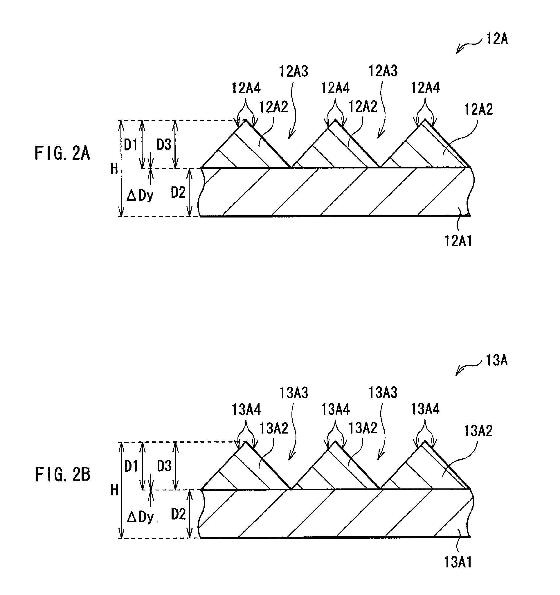
[0090]Next, a description will be given of examples of the lens film 12A or the like of this embodiment in comparison with the lens film 112 of comparative examples.

[0091]In the lens film 12A or the like according to the examples, the width (pitch) in the arrangement direction of the pole prism 12A2 or the like was 31 μm, the depth D1 of the valley 12A3 or the like was 15 μm, the angle of the top (apex angle) of the pole prism 12A2 or the like was 90 deg, and the thickness D2 of the transparent base 12A1 or the like was 50 μm. In addition, the depth of the depression 12B5 (13B5) (−ΔDx (=D3−D1)) was −4.31 μm, −3.13 μm, −2.46 μm, −2.04 μm, −1.21 μm, −0.5 μm, +0.0 μm, or +0.25 μm (refer to Table 1). The depth (−ΔDx) of +0.0 μm means that no skirt layer exists. The depth (−ΔDx) of +0.25 μm means that the skirt layer slightly remains due to an error in manufacturing or the like, that is, means that the skirt layer does not exist practically.

[0092]Meanwhile, in the lens film 112 according...


PUM


Abstract

A lens film with small warpage even when a transparent base is thin is provided. Pole prisms made of a hardening resin are arranged along the extending direction on a transparent base made of flexible material. The transparent base has a depression according to a valley between the pole prisms adjacent to each other. The pole prism has a sloping face extending to an inner wall of the he depression. The transparent base is in contact with the valley. A layer not functioning as a prism, that is, a so-called skirt layer does not exist between the transparent base and the pole prisms.

Description

CROSS REFERENCES TO RELATED APPLICATIONS[0001]The present invention contains subject matter related to Japanese Patent Application JP 2006-129633 filed in the Japanese Patent Office on May 8, 2006, and Japanese Patent Application JP 2006-240839 filed in the Japanese Patent Office on Sep. 5, 2006, the entire contents of which being incorporated herein by references.BACKGROUND OF THE INVENTION[0002]1. Field of the Invention[0003]The present invention relates to an optical sheet having convex shape on the surface, a method for producing it, and a display apparatus including the optical sheet.[0004]2. Description of the Related Art[0005]In these years, cathode ray tubes (CRT), which were a mainstream of display apparatuses in the past, have been replaced by liquid crystal display apparatuses, since the liquid crystal display apparatuses have advantages such as low electrical power consumption, space-saving feature, and low cost.[0006]There are several types of the liquid crystal display...

Claims


Application Information

Patent Timeline
IPC IPC(8): G02F1/1333
CPCG02B5/0294G02F1/133606G02B5/045G02B5/04G02F1/1335
Inventor KIMURA, KIYOHIROSASAKI, JUNAOKI, MAKOTOKUDO, YASUYUKIFUKUDA, MARIKOCHAKCHUNG, YU ANDREW
Owner SATURN LICENSING LLC
Why Eureka
Try Eureka