Aspheric multifocal diffractive ophthalmic lens

a multi-focal, diffractive technology, applied in the field of multi-focal ophthalmic lenses, can solve the problem of increasing the cost of lens making

Inactive Publication Date: 2007-11-08
VISION ADVANCEMENT LLC
View PDF25 Cites 79 Cited by
  • Summary
  • Abstract
  • Description
  • Claims
  • Application Information

AI Technical Summary

Problems solved by technology

Note, both surfaces, opposite and base surfaces may by structurally made multifocal surfaces but this would increase a cost of making the lens.

Method used


Image

  • Aspheric multifocal diffractive ophthalmic lens
  • Aspheric multifocal diffractive ophthalmic lens
  • Aspheric multifocal diffractive ophthalmic lens

Examples


Embodiment Construction

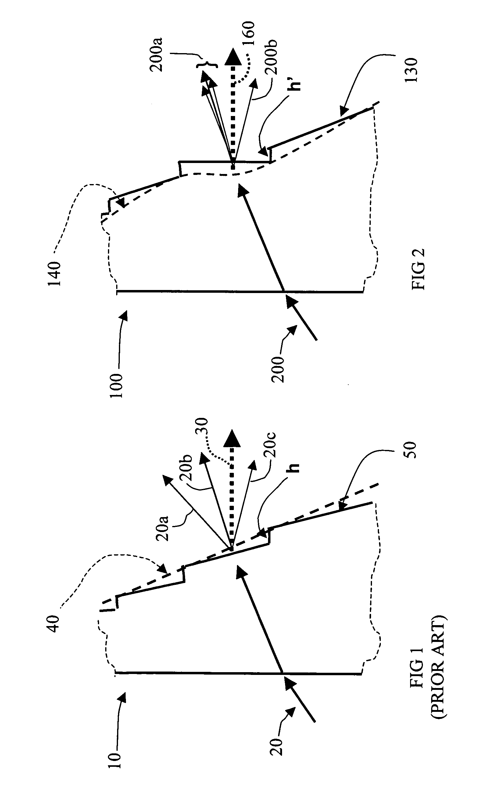
[0079]FIG. 1 describes a portion of a prior art diffractive lens 10 with blazed periodic structure 50 creating different diffraction orders indicating by the directions 20a, 20b, 20c, etc. along which the light can only be channeled. The figure includes input light ray 20 refracted by the lens 10. It also shows the refractive base curve 40 that would refract the exiting ray corresponding to the input ray 20 along the direction of zero-order diffraction 20b. Direction of (+1)-order diffraction is shown by 20a and (−1)-order diffraction by 20c. Theoretically, there are infinite orders of diffraction.

[0080]The FIG. 1 incorporates a reference to the “geometrical model” of diffractive lens by including blaze ray 30 as the ray corresponding to the input ray 20 and refracted by the blaze. The direction of the blaze ray 30 differs from the direction of 0-order diffraction 20b due to the different refraction angles of the rays at the base curve 40 and blaze structure 50. The angle difference...


PUM


Abstract

A multifocal ophthalmic lens includes a lens element having an anterior surface and a posterior surface, a refractive zone, or base surface having aspherically produced multifocal powers disposed on one of the anterior and posterior surfaces; and a near focus diffractive multifocal zone disposed on one of the anterior and posterior surfaces.

Description

[0001]The present application claims priority from U.S. Provisional Application Ser. No. 60 / 798,518 filed May 8, 2006, this referenced application being incorporated herein in it's entirety by this specific reference thereto.FIELD OF THE INVENTION[0002]The present invention relates generally to multifocal ophthalmic lenses, and more particularly to multifocal lenses which provide diffractive powers with improved intermediate vision associated with the enhanced depth of focus at distant vision.BACKGROUND OF THE INVENTION[0003]Ophthalmic lens is defined as a lens suitable for carrying on the eye or inside the eye. Also included are less common vision correction lenses such as artificial corneas and lamellar corneas implants. There is a significant effort to develop a lens for presbyopia correction in a form of refractive or diffractive type lenses.[0004]A fixed single power lens provides good quality of vision but only within a small range of viewing object distances that is usually s...

Claims


Application Information

Patent Timeline
Patent Type & Authority Applications(United States)
IPC IPC(8): G02B27/44
CPCA61F2/1618A61F2/1654A61F2002/164G02B3/08G02C2202/20G02C7/028G02C7/042G02C7/044G02B3/10A61F2/142A61F2/164G02B3/00G02B27/00G02C7/04
Inventor PORTNEY, VALDEMAR
Owner VISION ADVANCEMENT LLC
Why Eureka
Try Eureka