Fastening device

a technology of fastening device and clamping plate, which is applied in the direction of couplings, machines/engines, shock absorbers, etc., can solve the problem of relatively high amplitude, and achieve the effect of longer li

Active Publication Date: 2007-11-08
PUREM GMBH
View PDF15 Cites 4 Cited by
  • Summary
  • Abstract
  • Description
  • Claims
  • Application Information

AI Technical Summary

Benefits of technology

[0004]The present invention relates to the problem of providing an embodiment for a fastening devi...

Problems solved by technology

In the area of the resonant frequencies of the exhaust system and/or the respective component connected to the fastening device, said vibrations c...

Method used


Image

  • Fastening device
  • Fastening device
  • Fastening device

Examples


Embodiment Construction

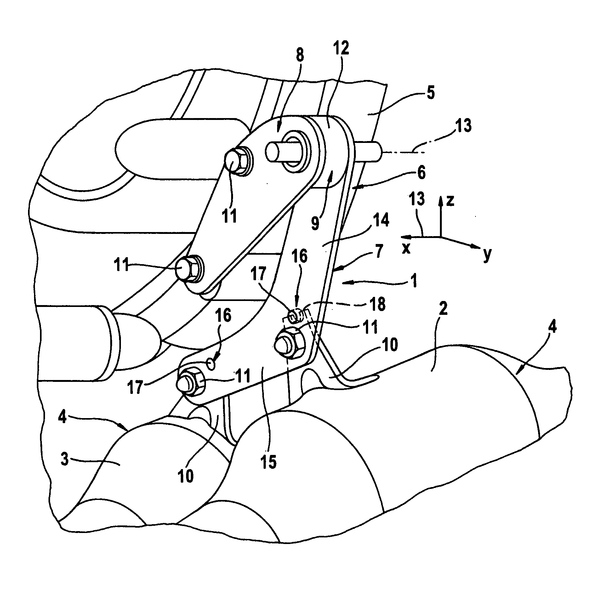
[0012]According to FIG. 1, a fastening device 1 with the help of which at least one of components 2, 3 of an exhaust system 4 can be attached to at least one member 5 of a motor vehicle 6, not otherwise shown here, includes a component leg 7, a member leg 8 and a coupling body 9. In the installed state shown here, the component leg 7 is rigidly or stiffly attached to the respective components 2, 3. The member leg 8 is rigidly or stiffly attached to the respective member 5 in the installed state. The two legs 7, 8 are attached to one another via the coupling body 9.

[0013]The components 2, 3 of the exhaust system 4 each may be a catalytic converter, for example. In the example shown here, the exhaust system 4 is designed with two lines of flow and accordingly has two exhaust lines through which exhaust gas can flow in parallel and each of which contains a catalytic converter 2, 3. The catalytic converters 2, 3 are arranged side-by-side in the area of the vehicle 6 shown in FIG. 1. Wit...


PUM


Abstract

The invention relates to a device for fastening at least one component of an exhaust system to at least one member of a motor vehicle, including a component leg that is designed for rigid fastening to the at least one component of the exhaust system and one member leg that is designed for rigid fastening to the at least one member of the motor vehicle. A coupling body with or made of an elastomer is provided, the coupling body being connected on the one hand fixedly to the component leg and on the other hand being fixedly connected to the member leg.

Description

FIELD OF THE INVENTION[0001]The present invention relates to a device for fastening at least one component of an exhaust system to at least one member of a motor vehicle.BACKGROUND OF THE INVENTION[0002]A fastening device of this type is characterized in that it must absorb comparatively great relative movements between the respective component on the exhaust end and the respective member on the vehicle end in the longitudinal direction of the exhaust system and therefore must have a corresponding elasticity. Such relative movements occur due to thermal expansion effects caused by the heating of the exhaust system during operation of the vehicle. To this end, such a fastening device may have one component leg which is fixedly mounted on the respective component in the installed state and one member leg that is fixedly mounted on the respective member in the installed state. The two legs can then be attached to one another by means of a coupling body, so that they are spaced a distan...

Claims


Application Information

Patent Timeline
IPC IPC(8): F16C11/04F01N13/08
CPCB60K13/04F01N13/1822F16F1/3732F16F7/1028Y10T403/454Y10T403/32606Y10T403/45Y10T403/32614F16L55/035
Inventor RIEKERS, RALFPROMMERSBERGER, HOLGER
Owner PUREM GMBH
Why Eureka
Try Eureka