Aircraft-engine trend monitoring system

a trend monitoring and aircraft engine technology, applied in the direction of testing/monitoring control systems, electrical control, instruments, etc., can solve the problems of limited or unavailable air travel by major commercial carriers between lower-population locales, low maintenance etc., to reduce the cost of piston-engine aircraft maintenance, reduce the cost of manufacturer's warranty, and enhance flight safety

Inactive Publication Date: 2007-11-08
GUARDIAN MOBILITY
View PDF23 Cites 45 Cited by
  • Summary
  • Abstract
  • Description
  • Claims
  • Application Information

AI Technical Summary

Benefits of technology

[0007] We have developed a way of predicting engine issues before they become problems and therefore reduce piston-engine aircraft maintenance cost significantly, while enhancing flight safety and reducing the manufacturer's warranty cost. In accordance with our approach, the outputs of engine-condition sensors are recorded periodically, preferably many times per minute, and the results are analyzed in such a fashion as to examine piston-engine performance trends and predict the need for engine maintenance. The result can be significantly reduced maintenance costs, because such monitoring makes it safe to lengthen the average time between expensive engine overhauls; overhauls can be pre-scheduled for longer intervals, with additional overhauls performed in the interim only when the results of sensor monitoring indicate the need for maintenance action.

Problems solved by technology

Although such requirements have contributed to the high level of safety that the flying public enjoys, that safety has come at a cost.
And this cost is particularly evident in relatively low-volume, short-distance routes.
Air travel by major commercial carriers between lower-population locales has tended to be limited or unavailable since such routes can be supported most cost-effectively by small aircraft in, e.g., “air-taxi” or “air-cab” services.

Method used


Image

  • Aircraft-engine trend monitoring system
  • Aircraft-engine trend monitoring system
  • Aircraft-engine trend monitoring system

Examples


Embodiment Construction

[0025] To provide an overall understanding, certain illustrative embodiments will now be described; however, it will be understood by one of ordinary skill in the art that the systems and methods described herein can be adapted and modified to provide systems and methods for other suitable applications and that other additions and modifications can be made without departing from the scope of the systems and methods described herein.

[0026] Unless otherwise specified, the illustrated embodiments can be understood as providing exemplary features of varying detail of certain embodiments, and therefore, unless otherwise specified, features, components, modules, and / or aspects of the illustrations can be otherwise combined, separated, interchanged, and / or rearranged without departing from the disclosed systems or methods.

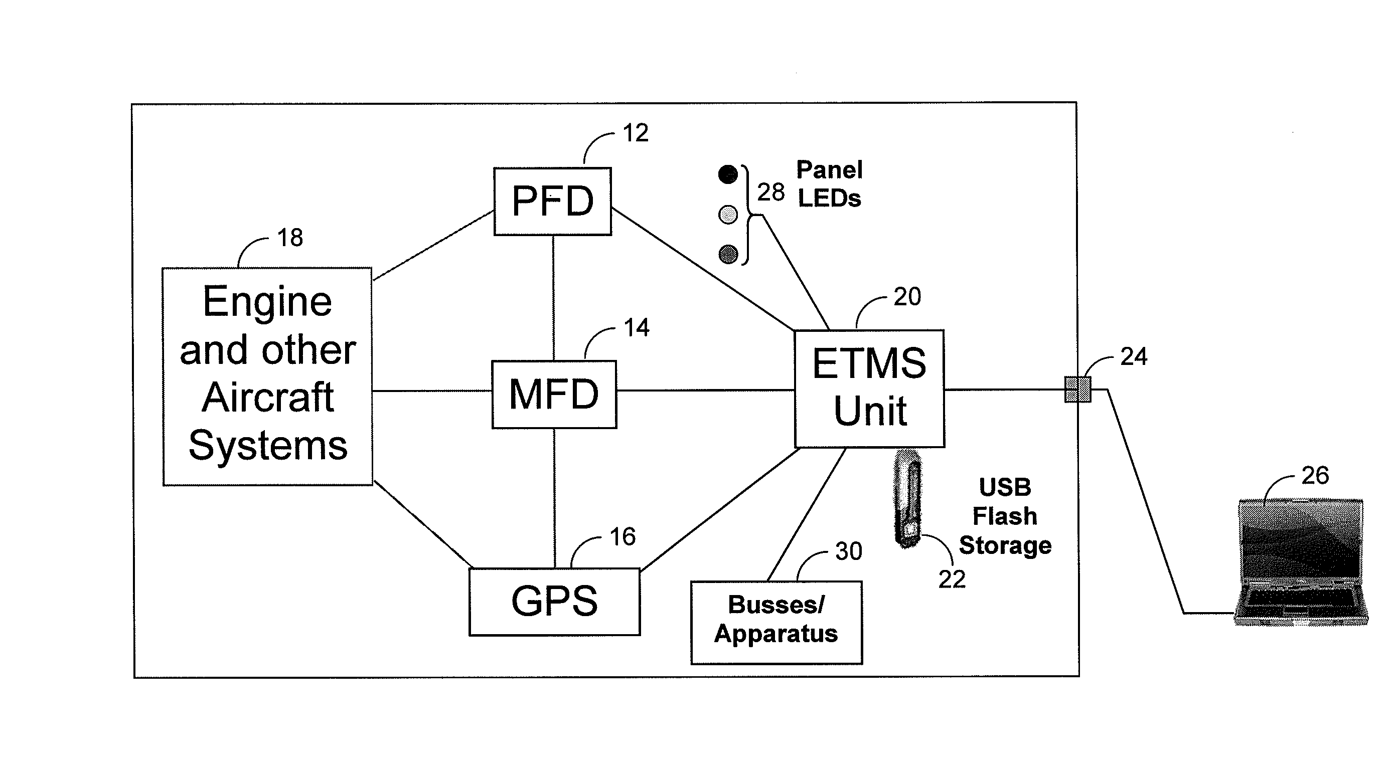
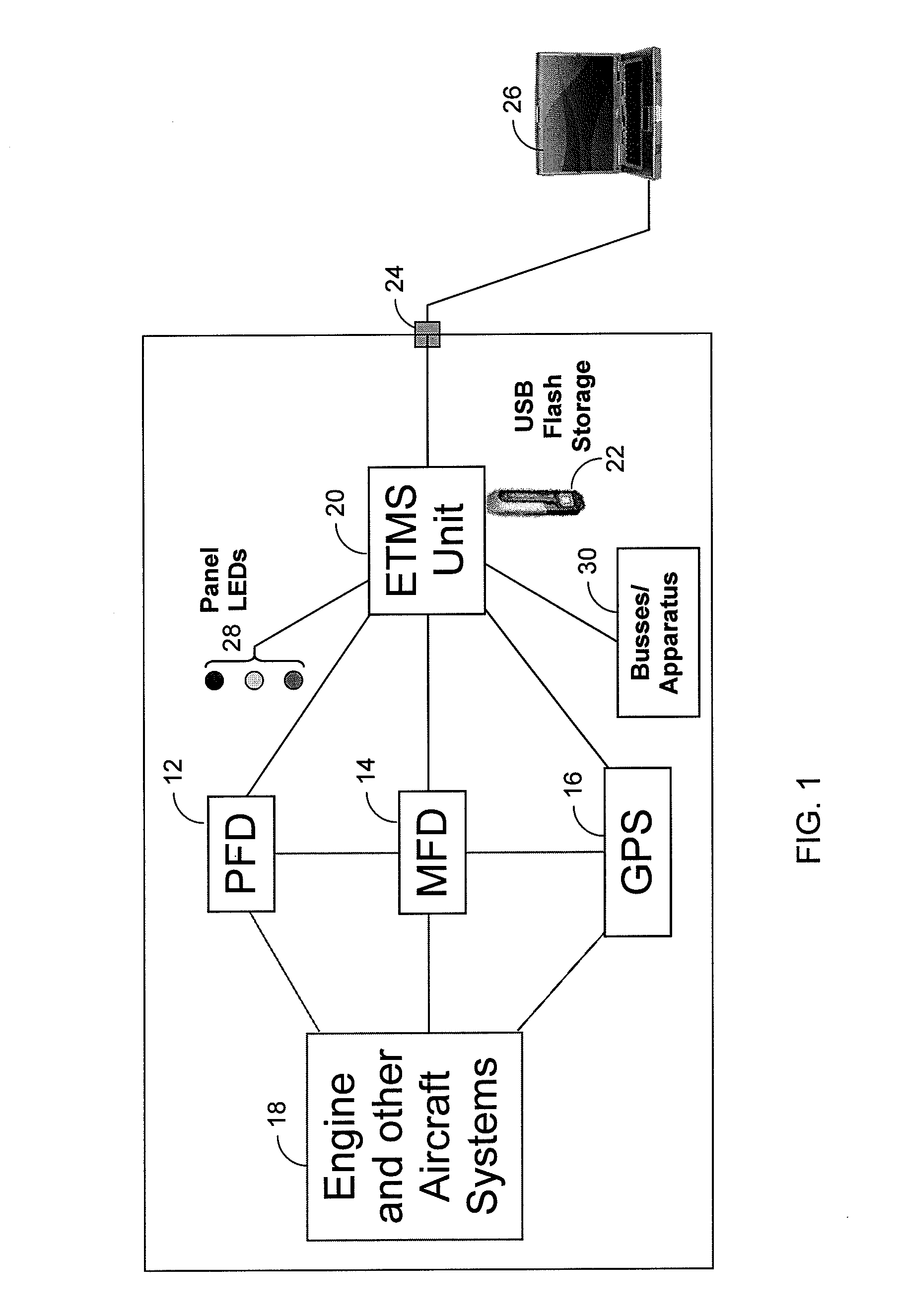
[0027]FIG. 1 depicts in block diagram form one type of system that may be employed to carry out the present invention's teachings. Conventionally, a small, piston-engin...


PUM

PropertyMeasurementUnit
temperatureaaaaaaaaaa
flight timeaaaaaaaaaa
temperatureaaaaaaaaaa

Abstract

Methods and systems for aircraft engine trend monitoring include periodically recording the outputs of engine-condition sensors and analyzing the results to examine piston-engine performance trends and predict the need for engine maintenance. Various analyses can be performed, separately or in parallel, including comparing the current parameter values with values recorded for that parameter in previous instances of similar operating conditions; comparing parameter values to predetermined nominal ranges; and detecting parameter values that exhibit trends over time that if followed would result in out-of-bound readings. Sensed parameter values can also be used to detect when recommended engine operating conditions are being exceeded. By using the results of the analyses to inform engine maintenance scheduling and provide alerts to the pilot and maintenance staff regarding recommended engine performance trends and/or operating condition exceedances, the methods and systems contribute to enhancing the level of safety that can be achieved despite significant maintenance-budget reductions.

Description

RELATED APPLICATIONS [0001] This application claims priority to, and incorporates by reference, the entire disclosure of U.S. Provisional Patent Application No. 60 / 744,038, filed on Mar. 31, 2006.BACKGROUND OF THE INVENTION [0002] 1. Field [0003] The present invention is directed to engine operation and maintenance. It finds particular, although not exclusive, application to piston-engine aircraft. [0004] 2. Background Information [0005] A large volume of personal travel occurs by air. For destinations of any distance, it is almost always the fastest travel mode and, in terms of injuries per passenger mile, the safest. The relative safety of that air transportation mode results from a number of factors. Among these are the stringent maintenance requirements that are imposed upon civil aviation. [0006] Although such requirements have contributed to the high level of safety that the flying public enjoys, that safety has come at a cost. And this cost is particularly evident in relative...

Claims


Application Information

Patent Timeline
Patent Type & Authority Applications(United States)
IPC IPC(8): G01L3/00
CPCF02D41/22Y02T10/40G07C5/085G05B23/0232
Inventor MORRISON, BRIAN D.HANVEY, STEPHAN A.WILKINSON, RONALD E.
Owner GUARDIAN MOBILITY
Why Eureka
Try Eureka