Harmonic gear drive

a gear drive and gear drive technology, applied in the direction of gearing, gearing elements, toothed gearings, etc., can solve the problems of product service life decline, reduce slippage, prevent product service life decline due to slippag

Active Publication Date: 2007-11-15
HONDA MOTOR CO LTD
View PDF8 Cites 24 Cited by
  • Summary
  • Abstract
  • Description
  • Claims
  • Application Information

AI Technical Summary

Benefits of technology

[0023]With this construction of the harmonic gear drive, providing rolling elements allows the contact area of the part where slippage may occur to be decreased. Therefore, it is possible to

Problems solved by technology

However, the harmonic gear drive 100 has a structure which indispensably causes noise.
Further, in the case of the harmonic gear drive 100 which is us

Method used


Image

  • Harmonic gear drive
  • Harmonic gear drive
  • Harmonic gear drive

Examples


first embodiment

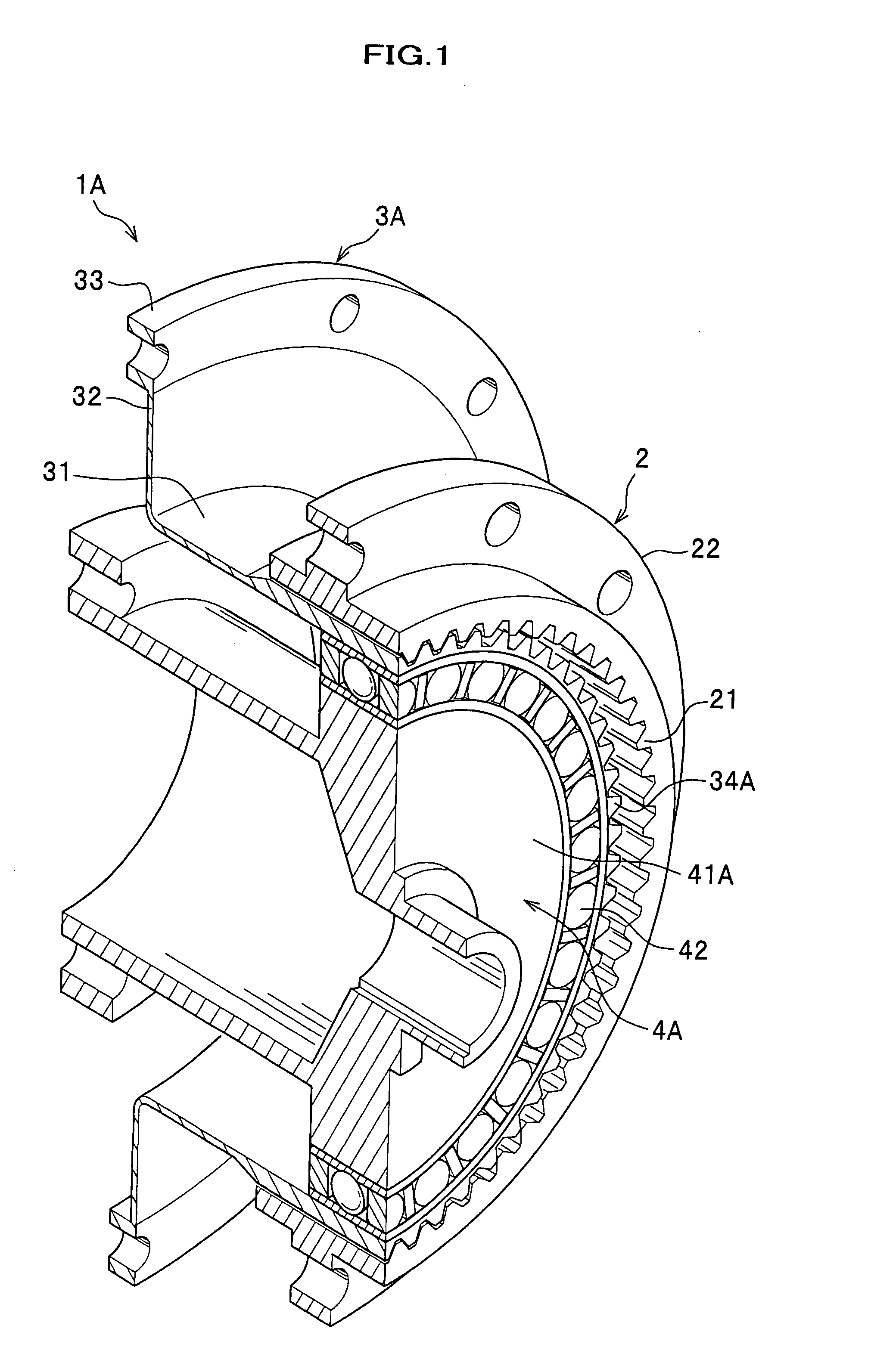
[0038]A harmonic gear drive according to the first embodiment will be described below.

[0039]As shown in FIG. 1, a harmonic gear drive 1A mainly consists of a rigid circular outer spline 2, a flexible circular inner spline which allows elastic deformation (i.e., flexspline) 3A, and a wave generator 4A.

[0040]The rigid circular outer spline 2 includes internal teeth (teeth portion) 21 provided along the inner periphery of the circular spline 2, and a rigid gear attachment portion 22 for fixing the outer peripheral portion of the rigid circular outer spline 2 to a stationary member (not shown).

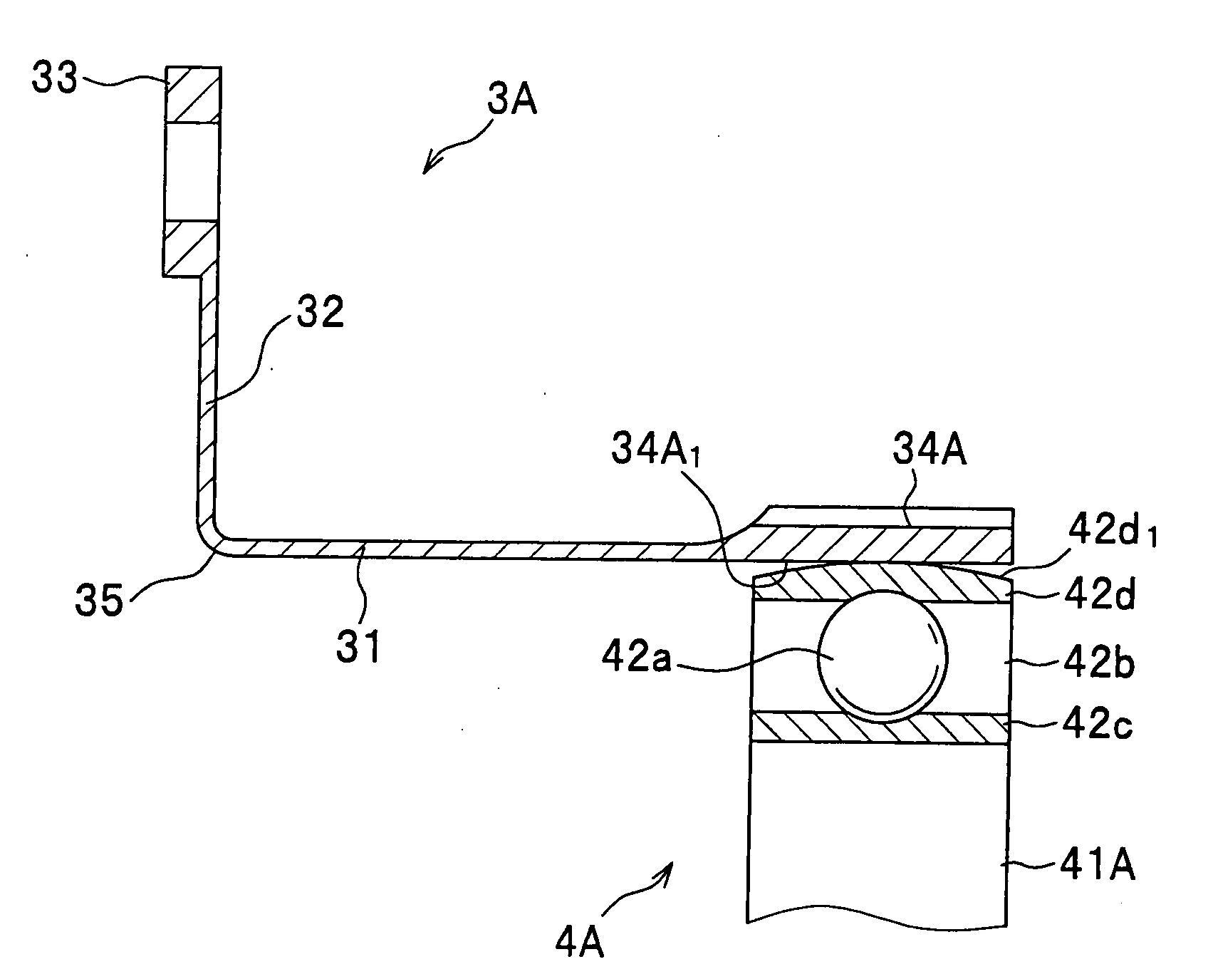
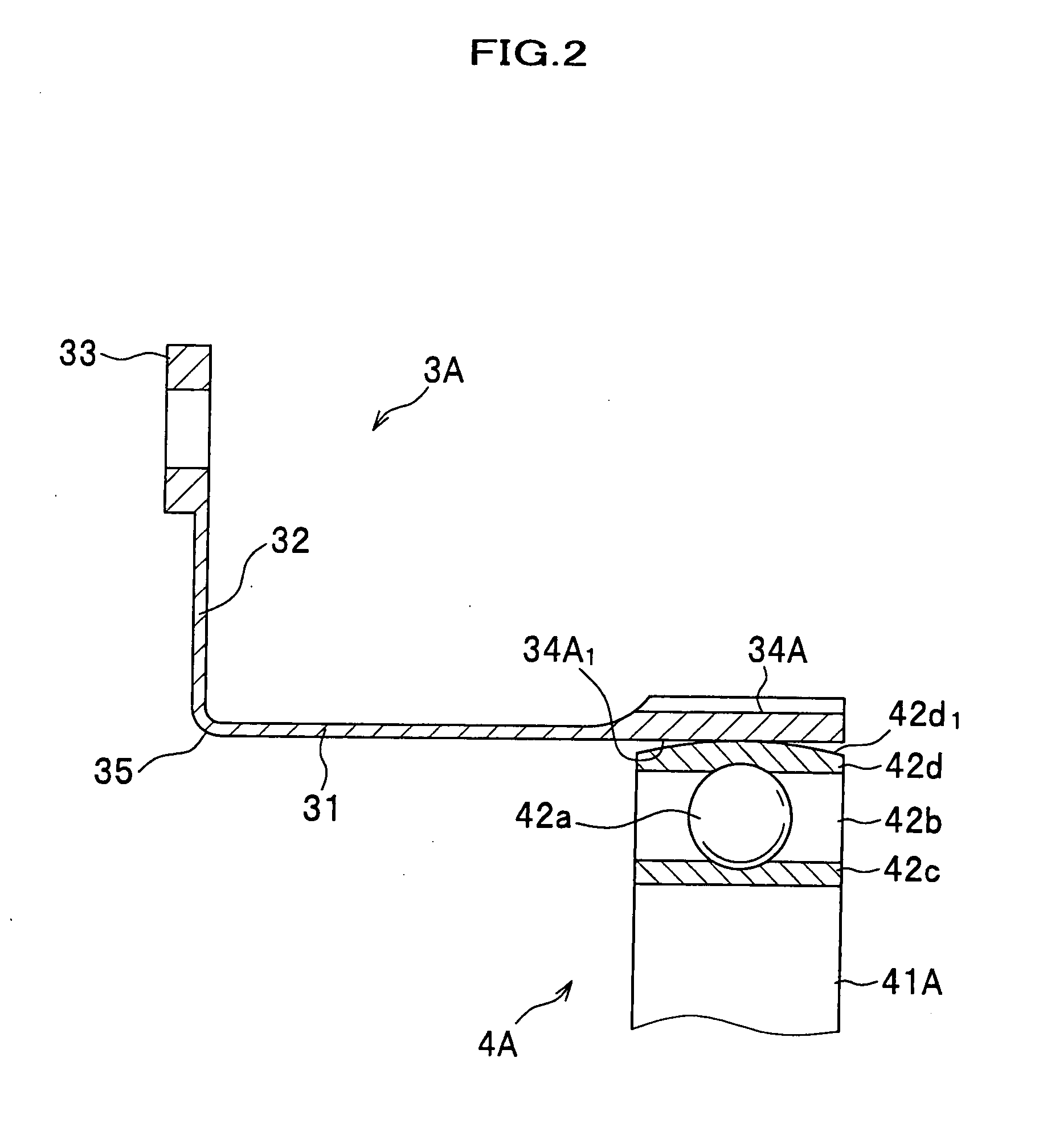
[0041]The flexspline 3A includes an attachment portion 33 which is joined to a power output member (not shown), and external teeth (teeth portion) 34A meshing with the internal teeth 21 of the rigid circular outer spline 2.

[0042]The attachment portion 33 is provided at one end of the flexspline 3A, and the external teeth 34A are provided at the other end of the flexspline 3A. The flexspline 3A is ...

second embodiment

[0067]A harmonic gear drive according to a second embodiment of the present invention will be described below, particularly with consideration given to differences from the harmonic gear drive 1A according to the first embodiment.

[0068]As shown in FIG. 4, a harmonic gear drive 1B according to the second embodiment includes a flexspline 3B and a wave generator 4B. Further, the harmonic gear drive 1B includes rolling elements (balls) 51 rotatably retained by a cage 52.

[0069]The flexspline 3B is provided with external teeth (teeth portion) 34B. A first recess 34B1 is formed in the inner peripheral surface of the teeth portion of the flexspline 3B. The first recess 34B1 is formed as a loop-shaped groove extending along the inner periphery of the teeth portion.

[0070]The wave generator 4B includes a cam portion 41B. It should be noted that the wave generator 4B is not furnished with a bearing. A second recess 41B1 is formed in the outer peripheral surface of the cam portion 41B. The secon...


PUM


Abstract

A harmonic gear drive includes a flexspline and a rigid spline which are meshed with each other, and a wave generator which deforms the flexspline to displace meshing points between the flexspline and the rigid spline. The length of each contact part between the flexspline and the wave generator always becomes shorter as viewed in a sectional plane containing a rotation axis of the wave generator than the width of the wave generator.

Description

CROSS REFERENCE TO RELATED APPLICATIONS[0001]This application claims the foreign priority benefit under Title 35, United States Code, §119(a)-(d) of Japanese Patent Application No. 2006-134001 filed on May 12, 2006 in the Japan Patent Office, the disclosure of which is herein incorporated by reference in its entirety.BACKGROUND OF THE INVENTION[0002]The present invention relates to a harmonic gear drive, which is compact in size and light-weighted, and which can realize high positional accuracy and high gear reduction ratios. More particularly, the present invention relates to a harmonic gear drive, which is suitable for applications in the field of automated machinery such as an articulation driving portion for a robot where silence and smoothness of driving are required, a semiconductor manufacturing device, and reduction gears for a precision actuator, and in the field of aerospace technology such as a control mechanism and a driving mechanism for aerospace machines.[0003]Harmoni...

Claims


Application Information

Patent Timeline
IPC IPC(8): F16H35/00
CPCF16H49/001Y10T74/19F16H2049/003F16H1/32F16H55/17
Inventor SAITO, YASUJI
Owner HONDA MOTOR CO LTD
Why Eureka
Try Eureka