Circumferentially pleated filter assembly and method of forming the same

a filter assembly and circumferential pleating technology, applied in the field of fluid filtration, can solve the problems of large hold-up volume of filter bags, difficult removal of used filter bags, and existing bag-type filters, so as to increase the effective surface area, reduce pressure drop, and increase the life of filters

Inactive Publication Date: 2007-11-15
3M INNOVATIVE PROPERTIES CO
View PDF54 Cites 5 Cited by
  • Summary
  • Abstract
  • Description
  • Claims
  • Application Information

AI Technical Summary

Benefits of technology

[0012] The subject disclosure is directed to a new and useful bag-type filter assembly, which includes an outer filter sleeve formed at least in part by a plurality of longitudinally extending pleats, and an inner filter sleeve formed at least in part by a plurality of longitudinally extending pleats. The concentric pleated filter sleeves provide a significant increase in the effective surface area of the filter assembly of the subject disclosure, as compared to conventional bag-type filters known in the art. The enhanced surface area increases the life of the filter, lowers pressure drop and lowers the operating costs for the customer. The concentric inner and outer filter sleeves define an annular fluid passage therebetween, which has a reduced hold-up volume as compared to conventional bag-type filters known in the art. This reduction in hold-up volume eases the removal of the filter assembly from its housing after the filter has exceeded its useful lifespan.
[0013] An inlet cap is secured to a first end of the inner and outer filter sleeves and it has at least one inlet port communicating with the fluid passage of the filter assembly. An end cap is secured to a second end of the inner and outer filter sleeves and it has an end surface closing the fluid passage. In a presently preferred embodiment of the disclosure, a sheath surrounds the downstream side of the outer filter sleeve to provide a smooth continuous surface to protect the filter media and aid in installation and removal from the basket. The sheath is formed from a material having a relatively open porosity, such as a polymeric mesh or screen. It also envisioned that a similar sheath would surround or otherwise protect the downstream side of the inner filter sleeve to further aid in the installation and removal of the filter from the basket.

Problems solved by technology

There are several disadvantages associated with existing bag-type filters.
One such disadvantage is that filter bags have a large hold-up volume.
Thus, removal of a used filter bag is quite difficult, because it can be relatively heavy.
A full filter bag could weigh as much as thirty pounds and it may contain hazardous substances, adding to the difficulty of removal.
However, these balloons are often cumbersome to handle.
Another disadvantage associated with existing bag filters is that they provide a limited amount of effective filtration area.
Efforts to increase the effective filtration area of existing bag filter have been limited because of the industry standardization of basket sizes.
Consequently, any increase in effective filtration area is limited by the requirement that the outer diameter of the filter cannot be altered.
For the most part, these prior art efforts have fallen short.
Consequently, there is a substantial amount of empty space between adjacent pleats at the outer periphery of the filter element.

Method used


Image

  • Circumferentially pleated filter assembly and method of forming the same
  • Circumferentially pleated filter assembly and method of forming the same
  • Circumferentially pleated filter assembly and method of forming the same

Examples


Embodiment Construction

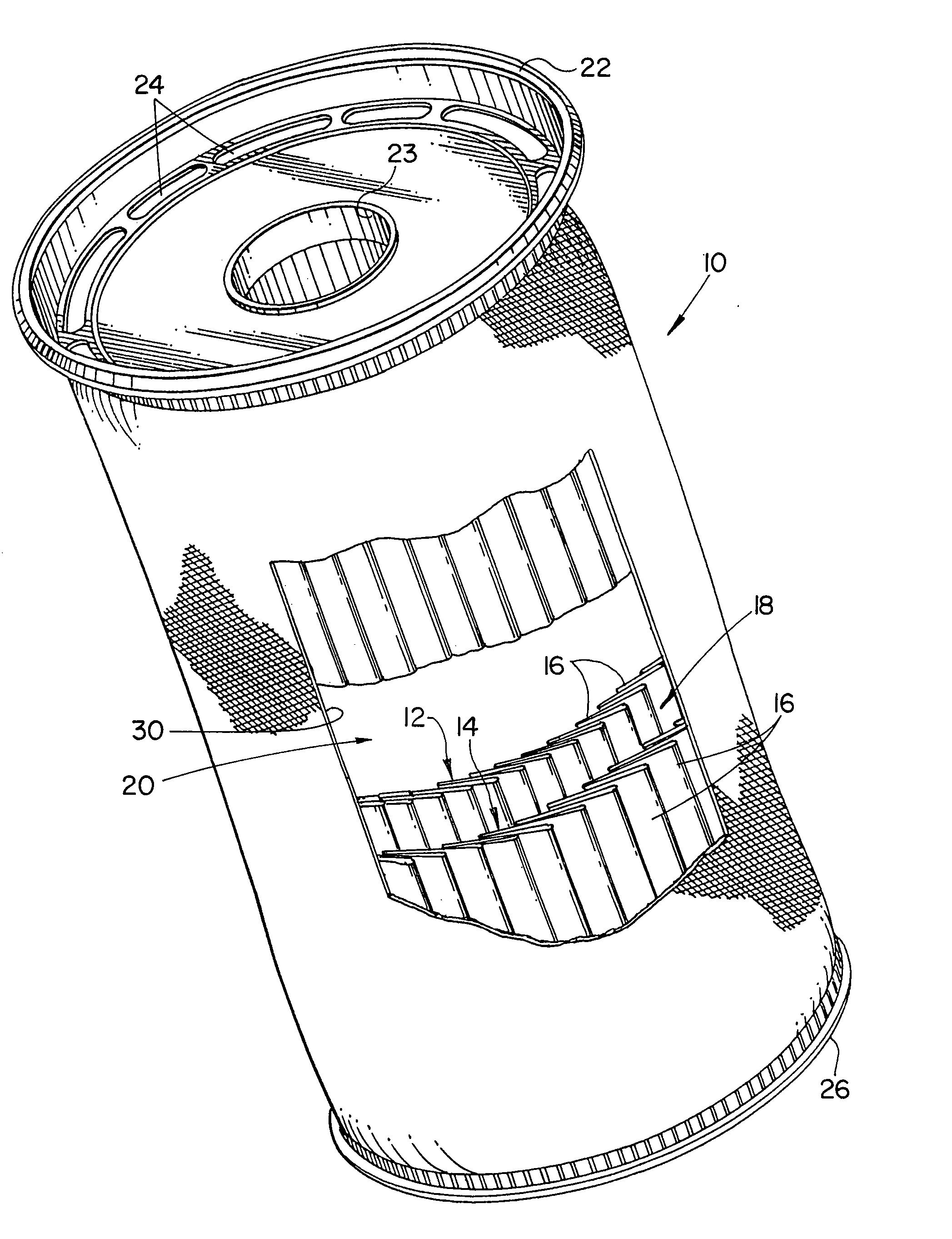
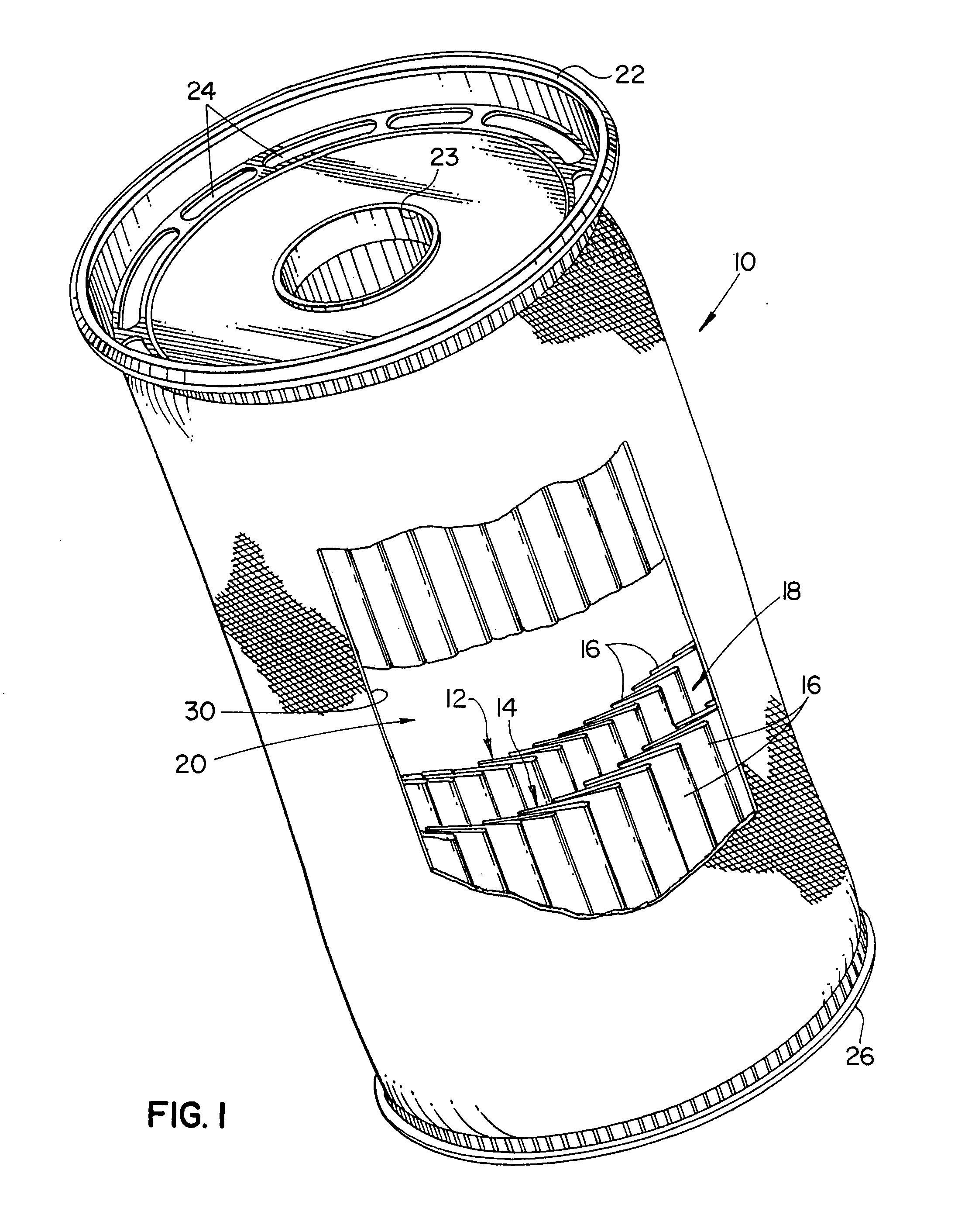
[0046] Referring now to the drawings wherein like reference numerals identify similar structural elements and / or features of the subject disclosure, there is illustrated in FIG. 1 a filter assembly constructed in accordance with a presently preferred embodiment of the subject disclosure and designated generally by reference numeral 10. Filter assembly 10 is a type of filter assembly commonly referred to as a bag-type filter, which is preferably collapsible and readily disposable after use.

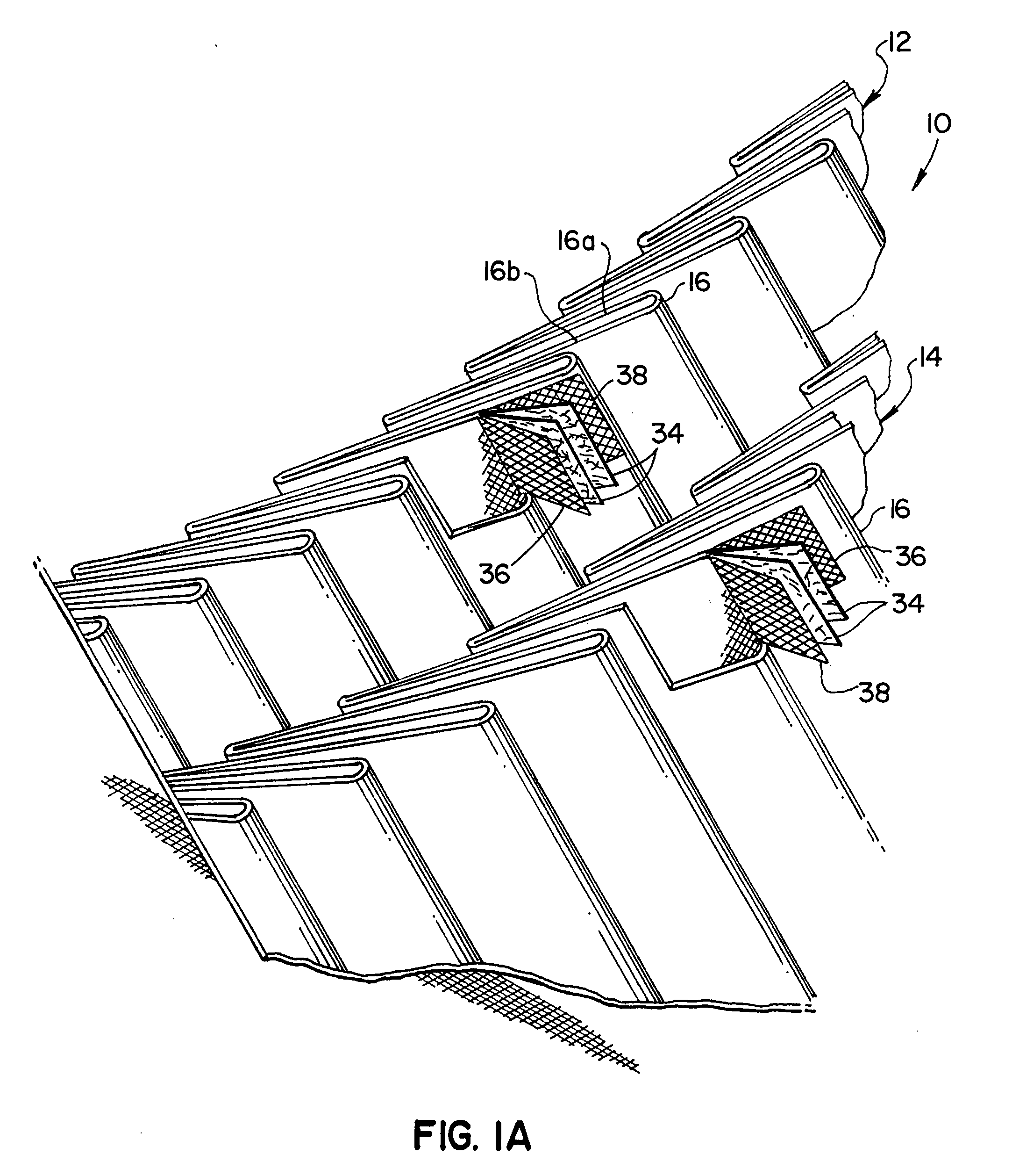
[0047] Referring to FIG. 1, the filter assembly 10 includes a generally cylindrical inner filter sleeve 12 and a generally cylindrical outer filter sleeve 14. The inner and outer filter sleeves 12, 14 are each formed, at least in part, from a plurality of longitudinally extending, circumferentially disposed arcuate pleats 16, which will be described in greater detail below. The pleats 16 are used to increase the amount of effective filtration area within the filter assembly relative to prior art b...


PUM

PropertyMeasurementUnit
arcuate height hoaaaaaaaaaa
arc lengthaaaaaaaaaa
arcuate heightaaaaaaaaaa

Abstract

A filter assembly is provided which includes an outer filter sleeve formed at least in part by a plurality of pleats, an inner filter sleeve formed at least in part by a plurality of pleats, wherein the inner and outer filter sleeves define a passage therebetween. An inlet cap is secured to a first end of the inner and outer filter sleeves and it has at least one inlet port communicating with the passage, and an end cap is secured to a second end of the inner and outer filter sleeves and it has an end surface closing the passage. Methods of forming such a filter assembly are also provided.

Description

RELATED APPLICATIONS [0001] This application is a continuation of U.S. application Ser. No. 10 / 993,824 filed Nov. 19, 2004, the disclosure of which is hereby incorporated by reference to the extent not inconsistent with the present application.BACKGROUND OF THE DISCLOSURE [0002] The subject disclosure is directed to fluid filtration, and more particularly, to a bag-type filter assembly having two concentric circumferentially pleated media sleeves defining an annular passage therebetween, which receives fluid for filtration. [0003] Bag-type filter systems for fluid filtration are well known in the art. These systems typically include a cylindrical housing, which is closed at one end and has a removable cover at the opposed end. An inlet conduit delivers fluid to be filtered into the housing and an outlet conduit removes filtered fluid from the housing. [0004] Replaceable bag filters are disposed within the housing in order to filter fluids delivered thereto. Typically, bag filters in...

Claims


Application Information

Patent Timeline
Patent Type & Authority Applications(United States)
IPC IPC(8): B01D29/07B01D39/00
CPCB01D29/111B01D2201/122Y10T156/1025Y10T156/1038Y10T156/1051B01D29/21B01D29/232B01D29/54
Inventor FALL, BRIAN L.HAMLIN, THOMAS J.PATEL, MAHESH Z.PULEK, JOHN L.SPEARIN, AARON
Owner 3M INNOVATIVE PROPERTIES CO
Why Eureka
Try Eureka