Portable gas powered internal combustion engine arrangement

a gas-powered internal combustion engine and portability technology, which is applied in the direction of combustion-air/fuel-air treatment, machines/engines, machine supports, etc., can solve the problems of limited utility of such a device, large and cumbersome devices, and inability to adapt, so as to maximize the gas flow, prevent the flow of liquid lpg, and maximize the surface area of lpg

Inactive Publication Date: 2008-09-16
LEHR IP LLC
View PDF33 Cites 26 Cited by
  • Summary
  • Abstract
  • Description
  • Claims
  • Application Information

AI Technical Summary

Benefits of technology

[0021]The gas provided to the carburetor is gas from the LPG contained in a Coleman Bottle arrangement of one or more Coleman Bottles. The Coleman Bottle type LPG container (whether called a Coleman Bottles or sold under any other brand name) in the arrangement is mounted on the mounting plate connected to the appropriate portion of the internal combustion engine to be in heat transfer and vibration transfer relationship thereto in a preferred orientation with respect to the horizontal. The Coleman Bottle may be of the configurations illustrated in U.S. design Pat. D295886. The Coleman Bottles may contain, in the smaller versions thereof, liquified petroleum gas on the order of 14 to 16 ounces. Such size LPG containers are the general type preferred for usage in the embodiments of the present invention. The preferred orientation is with the long axis of the Coleman Bottle LPG container at an angle of between 14° and 16°, with 15° being desired, for the present configuration of the Coleman Bottles. This angular orientation provides the very unusual and unexpected result of maximizing the gas flow and preventing the flow of liquid LPG from the Coleman Bottles. Since the Coleman Bottles are not filled to the top of the bottle with the LPG but have a predetermined and generally uniform from bottle to bottle volume of gas above the top surface of the LPG The selected angular orientation of the Coleman Bottles with respect to the horizontal is such that the surface area of the LPG is maximized but the outlet of the Coleman Bottles is vertically above the top surface of the LPG. Such orientation of the Coleman Bottles not only maximizes the usable surface area of the LPG from which the gas state is generated but also prevent the flow of LPG in the liquid state therefrom. The preferred angular orientation with respect to the horizontal may be selected for other LPG containers which may be utilized in other applications to achieve the unusual and novel configuration for evaporation of the gas from the liquid LPG. The Coleman Bottles have the additional advantage of being free from any requirement for a particular rotational position about its long axis for operation. That is, for the Coleman Bottles mounted as described herein, the Coleman Bottles may be in any rotational position about its axis and still provide operation.
[0022]The above described mounting of the Coleman Bottles on the mounting plate to be in thermal transfer relationship thereto for receiving heat as generated in the cylinder of the internal combustion engine as well as receiving vibration therefrom uniquely allows the continuous flow of larger amounts of gas from the LPG to thereby allow the powering of larger internal combustion engines and demand devices. The heat transferred to the Coleman Bottles heats the LPG contained therein to increase the evaporation of gas therefrom. The heat thus transferred to the LPG tends to keep the temperature of the liquid LPG above the freezing point even though comparatively larger amounts of gas are evaporated therefrom. The direct transfer of heat from the engine to the Coleman bottle and thus to the LPG therein has a dual benefit: the heat keeps the LPG from freezing and aids in cooling the internal combustion engine during the operation thereof. The transmittal of vibration of the Coleman Bottle by the operation of the engine also agitates the LPG to thus increase the effective surface area thereof thereby allowing even greater flow of gas therefrom and the agitation also helps in preventing the LPG from freezing.

Problems solved by technology

However, the storage of gasoline is highly restricted as to the type of container in which it may be stored, the places where it may be stored, the amount that may be stored and the environmental conditions under which it may be stored.
Such devices are, of course, large and cumbersome and not adapted to be a readily portable device that may be easily carried by one person and transported from location to location.
However, there is a demand for an electric power generator that is small and light enough to be moved by one person from location to location and still provide a moderate amount of electrical power.
Such a configuration limits the utility of such a device.
However, the gas flow rate of the gas from the LPG in a Coleman Bottle is limited because of the comparatively small surface area of the LPG from which the gas is generated.
Consequently, despite the attractiveness of the Coleman Bottles for use in many devices, the use of the Coleman Bottles has generally been limited to very low power requirement applications and have not been adapted for use in providing the energy for powering an internal combustion engine utilized to drive an electrical generator or other portable engine driven devices.

Method used


Image

  • Portable gas powered internal combustion engine arrangement
  • Portable gas powered internal combustion engine arrangement
  • Portable gas powered internal combustion engine arrangement

Examples


embodiment 10

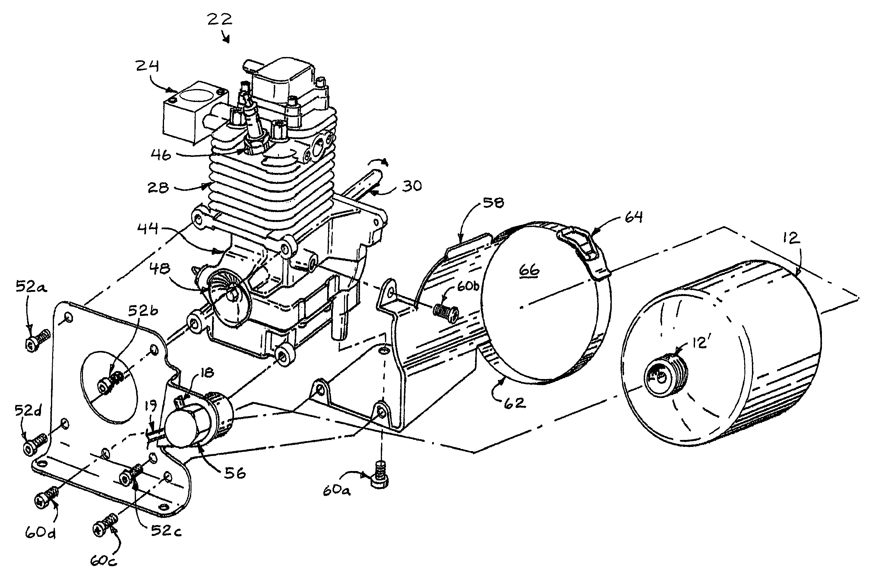
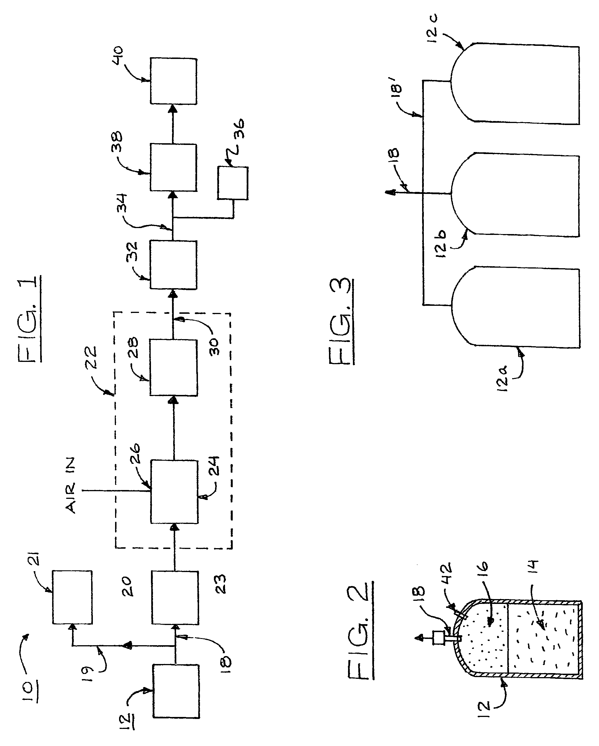
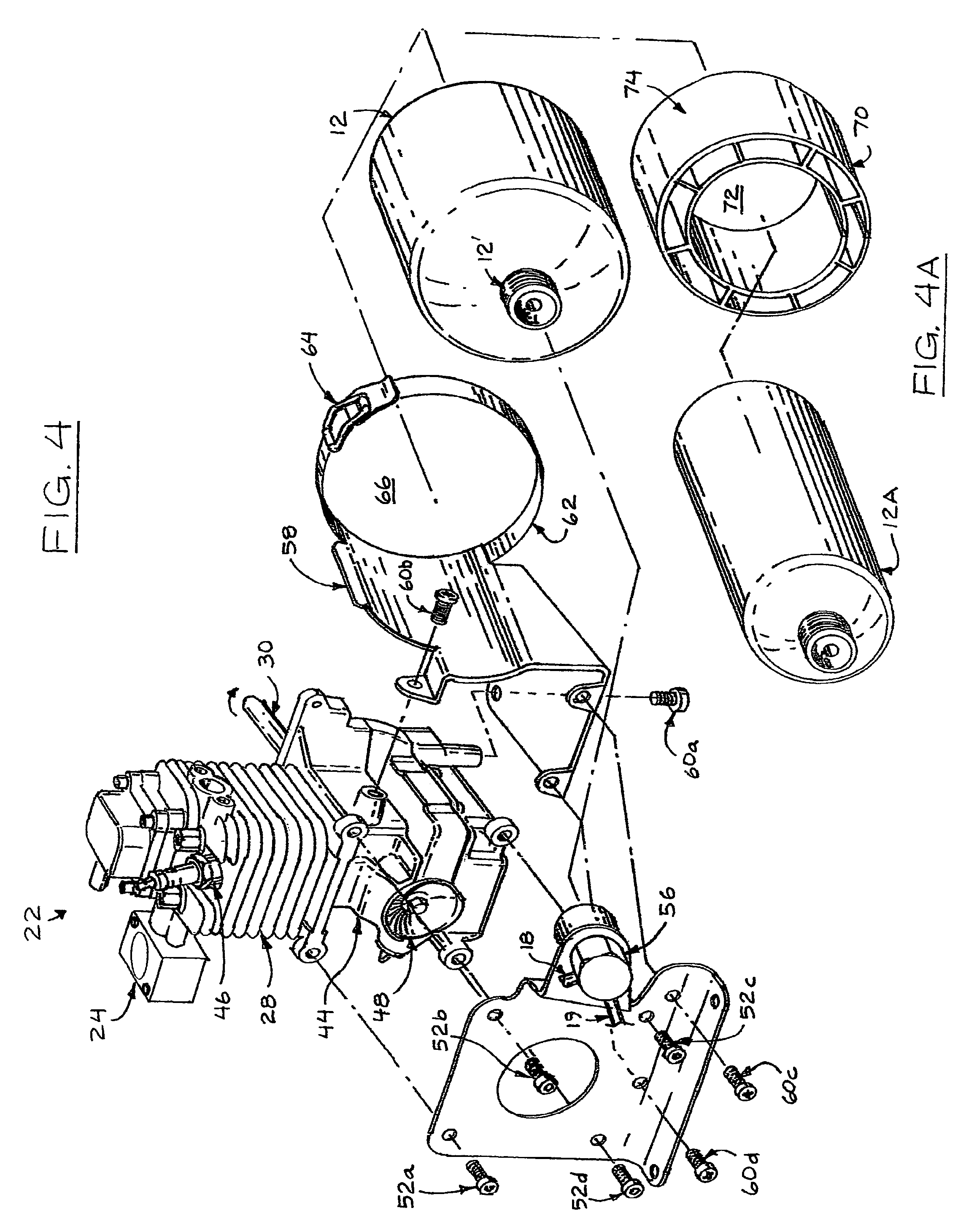
[0043]The gas 16 flowing from the pressure regulator 20 is directed through a conduit 23 into a carburetor 24 that is part of the internal combustion engine 22. The carburetor 24 has an air intake as indicated at 26. The carburetor 24 mixes the gas 16 with the air and provides the mixture to the cylinder 28 of the internal combustion engine 22 in a manner well known. The internal combustion engine 22 has a rotating output shaft 30. In the embodiment 10 the rotating output shaft drives an electric generator 32. The electric generator 32 provides electric energy as indicated at 34 and may be, for example in the power range of 300 to 1000 watts though larger power generators may be utilized in other applications. The electric energy may, if desired, be directed to provide 12 volt DC current as indicted at 36 or may be passed into an invertor 38 for conversion to 120 volts AC, 60 cycle as indicted at 40.

[0044]As noted above, the internal combustion engine 22 may be a four stroke, or two...

embodiment 100

[0053]FIG. 10 illustrates an embodiment 100 of the present invention as utilized to power an trimmer 102. As shown on FIG. 10, there is provided an internal combustion engine 22 powered by gas from an LPG container 12 and the internal combustion engine 22 rotates an output shaft 30′ to rotate the trimmer. Thus, the internal combustion engine and LPG container replace the gasoline powered engine and gasoline tank often utilized in such applications.

[0054]FIG. 11 illustrates an embodiment 110 of the present invention in which an internal combustion engine 22 powered by the gas from an LPG container 12 drives a fan 112 to provide a leaf blower 114. In embodiment 110 the internal combustion engine 22 and LPG bottle 12 replace the gasoline powered internal combustion engine and gasoline storage tank often utilized in such applications.

[0055]As described above, there is provided by the present invention a convenient and safe internal combustion engine driven by the gas generated from the ...


PUM


Abstract

A gas powered internal combustion engine in which the gas is provided from pressurized liquid gas in an LPG container and in which the LPG container is rigidly mounted adjacent to the internal combustion engine at a preselected angle to be in conductive heat transfer relationship to the internal combustion engine and in vibration receiving relationship to the internal combustion engine whereby the liquified gas in the LPG container is heated and the effective surface area thereof is increased.

Description

BACKGROUND OF THE INVENTION[0001]1. Field of the Invention[0002]This invention relates to a gas powered internal combustion engine which may be utilized to drive a variety of devices and may be utilized in one application as an emergency power source for generating electrical power. As utilized herein the term “gas” refers to a fluid in the gas state as a product which is emitted from a fluid in the liquid state which is stored under pressure and as contained, for example, in an LPG: Liquefied Petroleum Gas, commonly known as propane, container, or butane or the like. As utilized herein, the terms gas state, liquid state and fluid are used in the technical sense. That is, fluid is defined to mean a substance that can fill the volume of the container in which it is placed and includes both gas state and liquid state of the substance. “Gasoline” is used herein to define the liquid hydrocarbon based fuels generally used to power the engines of automobiles, trucks and the like.[0003]2. ...

Claims


Application Information

Patent Timeline
Patent Type & Authority Patents(United States)
IPC IPC(8): F02G5/00F02B67/00
CPCF02B43/10F02M21/06F02M21/029F02M21/0212F02M21/0221F02M21/0239F02M21/0287F02B63/02F02B63/04F02B65/00Y02T10/32Y02T10/30F02M21/02F02B63/00F02D19/02
Inventor HERZER, BERNARDO J.
Owner LEHR IP LLC
Why Eureka
Try Eureka