Optical component cleanliness and debris management in laser micromachining applications

a technology of optical components and micromachining, applied in the direction of manufacturing tools, transportation and packaging, active medium materials, etc., can solve the problem of the highest probability of damage in the input window, and achieve the effects of reducing the contamination of optical system components, maximizing gas flow, and reducing turbulence-induced beam motion

Active Publication Date: 2012-11-27
ELECTRO SCI IND INC
View PDF6 Cites 9 Cited by
  • Summary
  • Abstract
  • Description
  • Claims
  • Application Information

AI Technical Summary

Benefits of technology

[0010]Preferred embodiments of a purge gas port, laser beam attenuating input window, and laser shutter constitute subsystems of a UV laser optical system in which the light beam path is completely enclosed to reduce contamination of the optical system components. Purge gas is injected through multiple, e.g., nine, different locations in a beam tube assembly to make certain that the optical component surfaces sensitive to contamination are in the flow path of the purge gas. Clean, dry air is preferred over an inert purge gas because of the availability of compressed air in semiconductor device fabrication facilities and the absence of ozone formation at the preferred 355 nm operating wavelength. All of the beam tube assembly components are preferably made from nickel plated aluminum, stainless steel, brass, and Teflon® materials because of their outgasing properties. The flow level of the purge gas is determined by two criteria: (1) maximize gas flow without generating turbulence in the beam spot on the work surface, and (2) provide a minimum number of air volume exchanges each hour. Five air volume exchanges each hour are chosen as a minimum for the embodiment described. Porous diffusers are used at the purge gas injection points to reduce turbulence-induced beam motion. Purge gas flow in a controlled environment containing the laser beam path allows the laser rail to last longer than one that is not equipped with purge gas flow through a beam tube assembly.
[0011]An input window functioning as a fixed level attenuator is formed of a transparent optical material including, for example, but not limited to, fused silica with plano-plano surfaces oriented at 45 degrees with respect to the incident laser beam for S-polarization. Since this optical component acts as the input window assembly into a sealed optical assembly, it is desirable to have a mounting system that is resistant to perturbations from mechanical components sealing the optical system (in this case, the covers) that would in turn cause potential misalignment of the laser beam. Preferred mounting hardware is, therefore, resistant to any stresses caused by the covers as it accomplishes beam attenuation and damage prevention. Lastly, since it sees the highest W / cm2, and is exposed to the external environment, the input window has the highest probability of damage resulting from external contaminants polymerizing or burning onto the outer surface. The input window is, therefore, slightly offset from the centerline of the laser beam and is of sufficient size so that, if a burn occurred, the input window could be rotated to a new “clean” portion of the optical surface. When the input window is rotated in response to damage to the external optical surface, no additional beam steering occurs. When the covers are installed to seal the optical assembly, no additional beam steering occurs from the stresses of the cover fitted on the opto-mechanical assembly.
[0012]A laser shutter composed of pneumatic cylinder retracts and extends to position a metal shutter blade out of and into the path of the laser beam. A magnetic reed switch senses the position of the cylinder and feeds a position signal back to a system control computer. In the blocked state, the shutter blade reflects the laser beam into a feature of a structural gusset to safely attenuate the beam. The shutter mechanism is partly covered and shares a clean air purge source with the bulk of the laser optical assembly. Three laser shutter design features include (1) portions of the mechanism exposed to laser light are made from non-outgasing materials to limit optical contamination; (2) the pneumatic cylinder imparts a motive force to the shutter blade that does not contain materials likely to cause contamination of the optical components and does not generate heat and thereby ensures that beam steering resulting from the heat generation is kept to a minimum; and (3) features containing and attenuating the reflected / blocked beam are integral to the assembly and require no external components.
[0013]The shutter blocks the laser radiation directly after it emanates from the output window of the laser head. This occurs automatically upon disruption of the laser safety-interlock circuits or through manual command of the system control computer. Waste heat generated by the shutter actuator and the presence of materials known to cause optical component contamination are eliminated through the use of this device.

Problems solved by technology

Lastly, since it sees the highest W / cm2, and is exposed to the external environment, the input window has the highest probability of damage resulting from external contaminants polymerizing or burning onto the outer surface.

Method used


Image

  • Optical component cleanliness and debris management in laser micromachining applications
  • Optical component cleanliness and debris management in laser micromachining applications
  • Optical component cleanliness and debris management in laser micromachining applications

Examples


Embodiment Construction

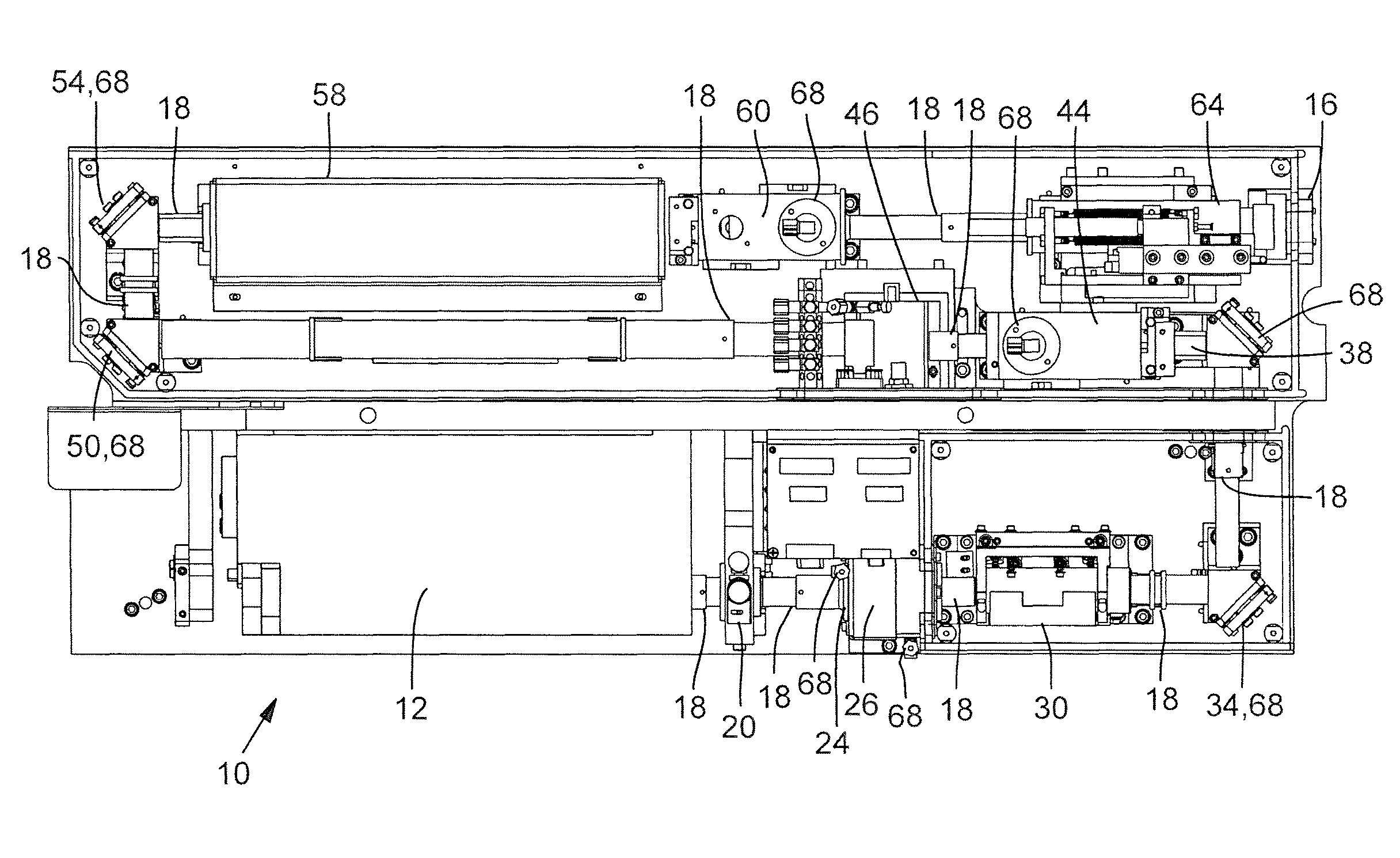
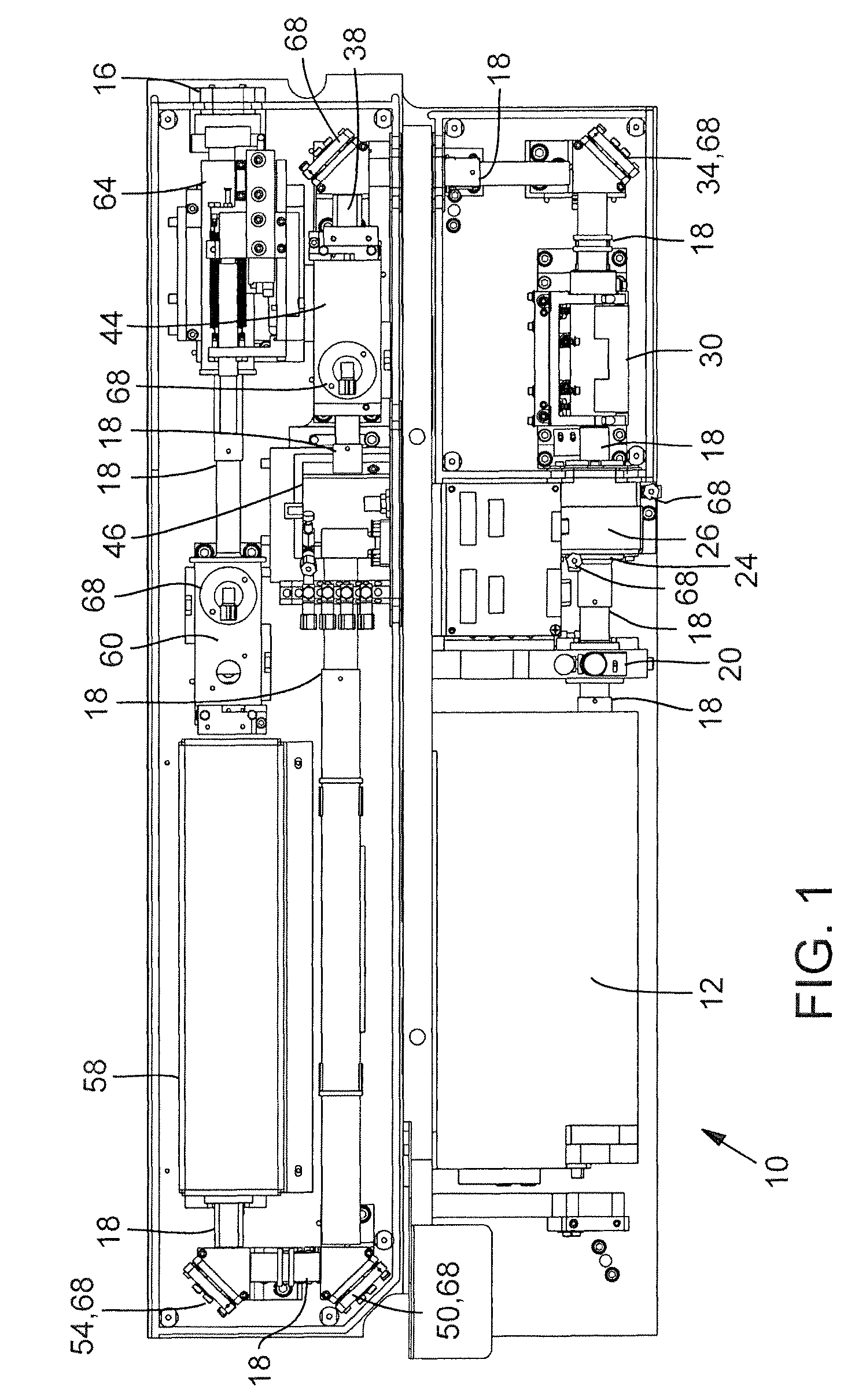
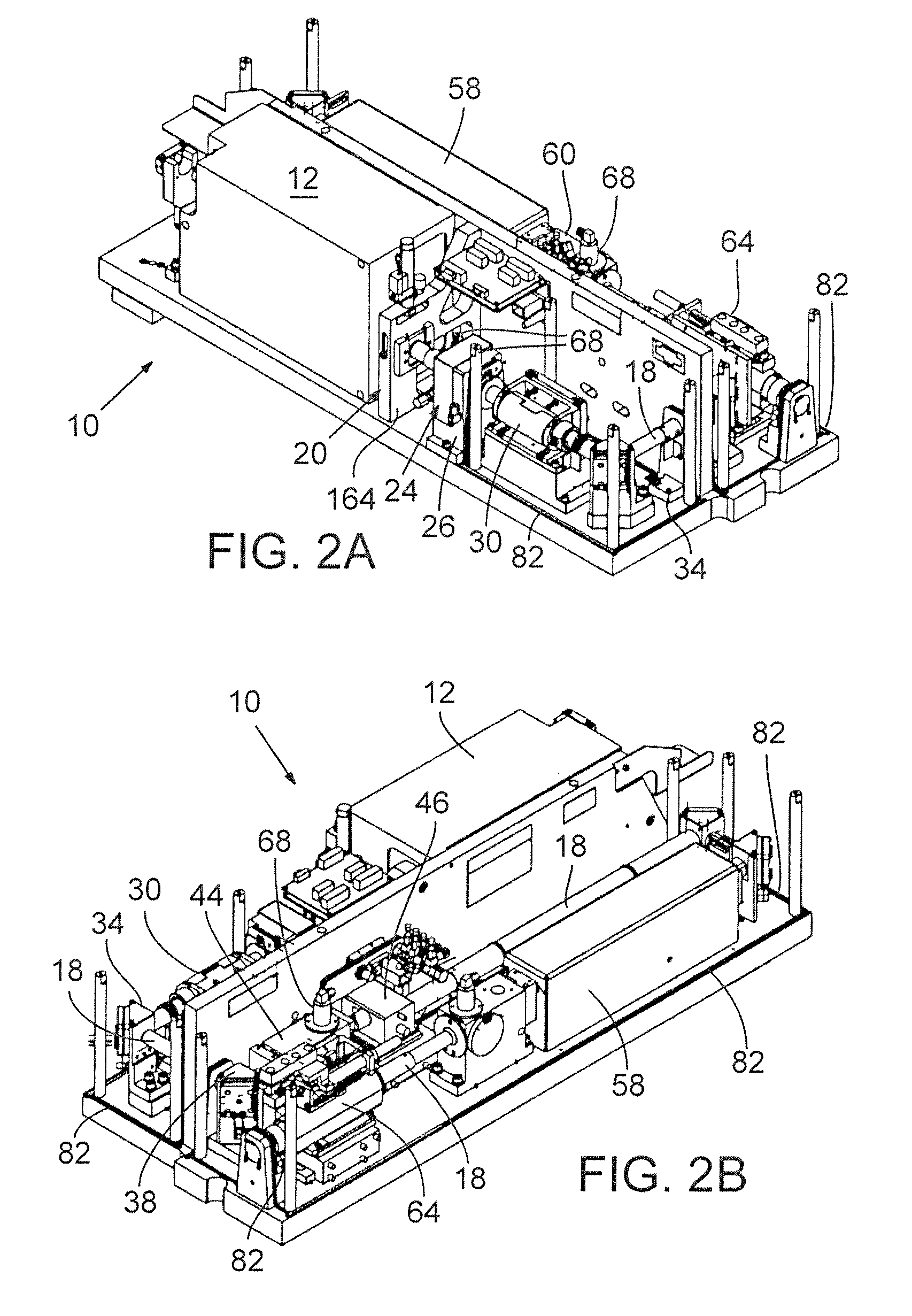
[0022]The laser optical system in which preferred embodiments of the above-summarized three subsystems are included is shown in FIGS. 1, 2A, and 2B. FIG. 1 is a plan view of a laser optical system 10 with its cover removed, and FIGS. 2A and 2B are isometric views of opposite sides of the laser optical system 10 of FIG. 1, showing where a laser head and a spatial filter, respectively, are located. FIGS. 1, 2A, and 2B show the laser rail assembly without the outer covers that seal the entire laser optical system 10. All of the beam tube sets 18 are visible in these three drawing figures and are specifically identified in FIG. 1.

[0023]With reference to FIGS. 1, 2A, and 2B, the output beam of a laser head 12 (housed within a separate cover) propagates along a beam path in the general shape of an “S” through an exit window 16 of laser optical system 10. The output beam propagates through the interior regions of multiple beam tube sets 18 to and from enclosed optical components positioned...


PUM

PropertyMeasurementUnit
operating wavelengthaaaaaaaaaa
pressureaaaaaaaaaa
angleaaaaaaaaaa

Abstract

Preferred embodiments of a purge gas port, laser beam attenuating input window, and laser shutter constitute subsystems of a UV laser optical system in which a laser beam is completely enclosed to reduce contamination of the optical system components. Purge gas is injected through multiple locations in a beam tube assembly to ensure that the optical component surfaces sensitive to contamination are in the flow path of the purge gas. The input window functions as a fixed level attenuator to limit photopolymerization of airborne molecules and particles. Periodically rotating optical elements asymmetrically in their holders reduces burn damage to the optics.

Description

RELATED APPLICATION[0001]This application claims benefit of U.S. Provisional Patent Application No. 60 / 742,162, filed Dec. 1, 2005.COPYRIGHT NOTICE[0002]© 2006 Electro Scientific Industries, Inc. A portion of the disclosure of this patent document contains material that is subject to copyright protection. The copyright owner has no objection to the facsimile reproduction by anyone of the patent document or the patent disclosure, as it appears in the Patent and Trademark Office patent file or records, but otherwise reserves all copyright rights whatsoever. 37 CFR §1.71(d).TECHNICAL FIELD[0003]The present disclosure relates to laser-based workpiece processing systems and, in particular, to optical component cleanliness and debris management in laser micromachining applications performed in such systems.BACKGROUND INFORMATION[0004]The state of the art for sealing laser beam paths in semiconductor processing equipment entails enclosing the entire optics volume with a cabinet style enclo...

Claims


Application Information

Patent Timeline
Patent Type & Authority Patents(United States)
IPC IPC(8): H01S3/22H01S3/223
CPCB23K26/0643B23K26/12B23K26/142B23K26/128B23K26/064B23K26/14B23K26/02H01S3/10
Inventor BOLT, BRYAN C.HEMENWAY, DAVID M.KOSMOWSKI, MARKLERNER, A. GREYNILSEN, BRADY E.POPE, RICHARD
Owner ELECTRO SCI IND INC
Why Eureka
Try Eureka