Retractable multiple winglet

Inactive Publication Date: 2007-11-15
GRANT ROGER HUGH
View PDF11 Cites 32 Cited by
  • Summary
  • Abstract
  • Description
  • Claims
  • Application Information

AI Technical Summary

Benefits of technology

[0003] Wingtip vortices are produced by high pressure air at the bottom of the wing traveling around the tips to reach the low pressure air at the upper surfaces of the wing. This creates a localized upwash in the region immediately outboard of each wingtip. This upwash decreases in strength as the point of measurement moves farther outboard away from the wingtip. Small airfoils (winglets) that extend outward into this upwash could recycle much of this energy back into usable lift and (to a lesser degree) thrust while reducing the strength of the vortex. This will add to the overall lift of the win

Problems solved by technology

This creates a localized upwash in the re

Method used


Image

  • Retractable multiple winglet
  • Retractable multiple winglet
  • Retractable multiple winglet

Examples


Embodiment Construction

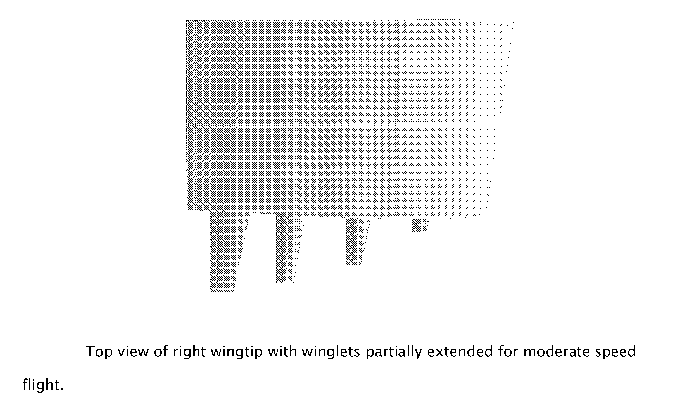
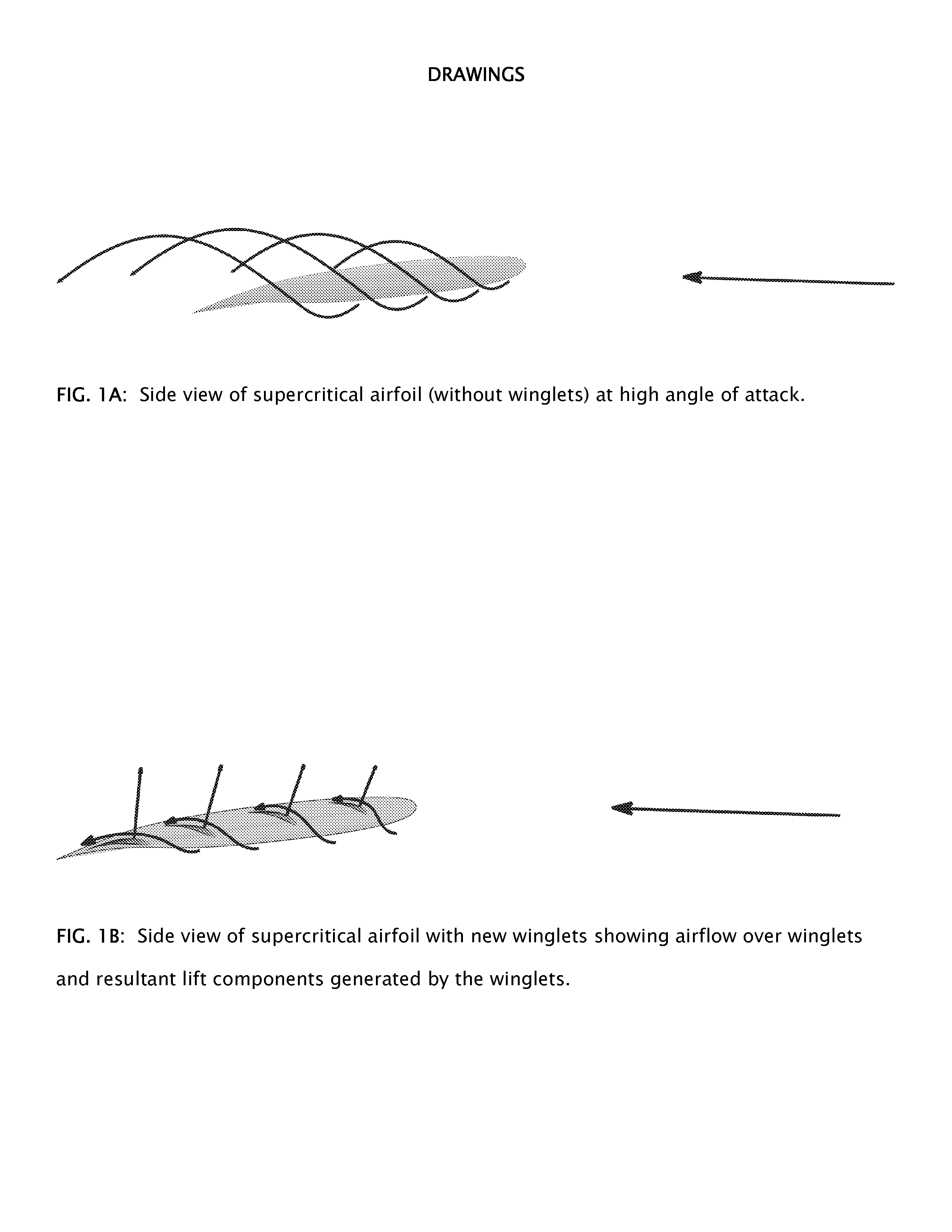
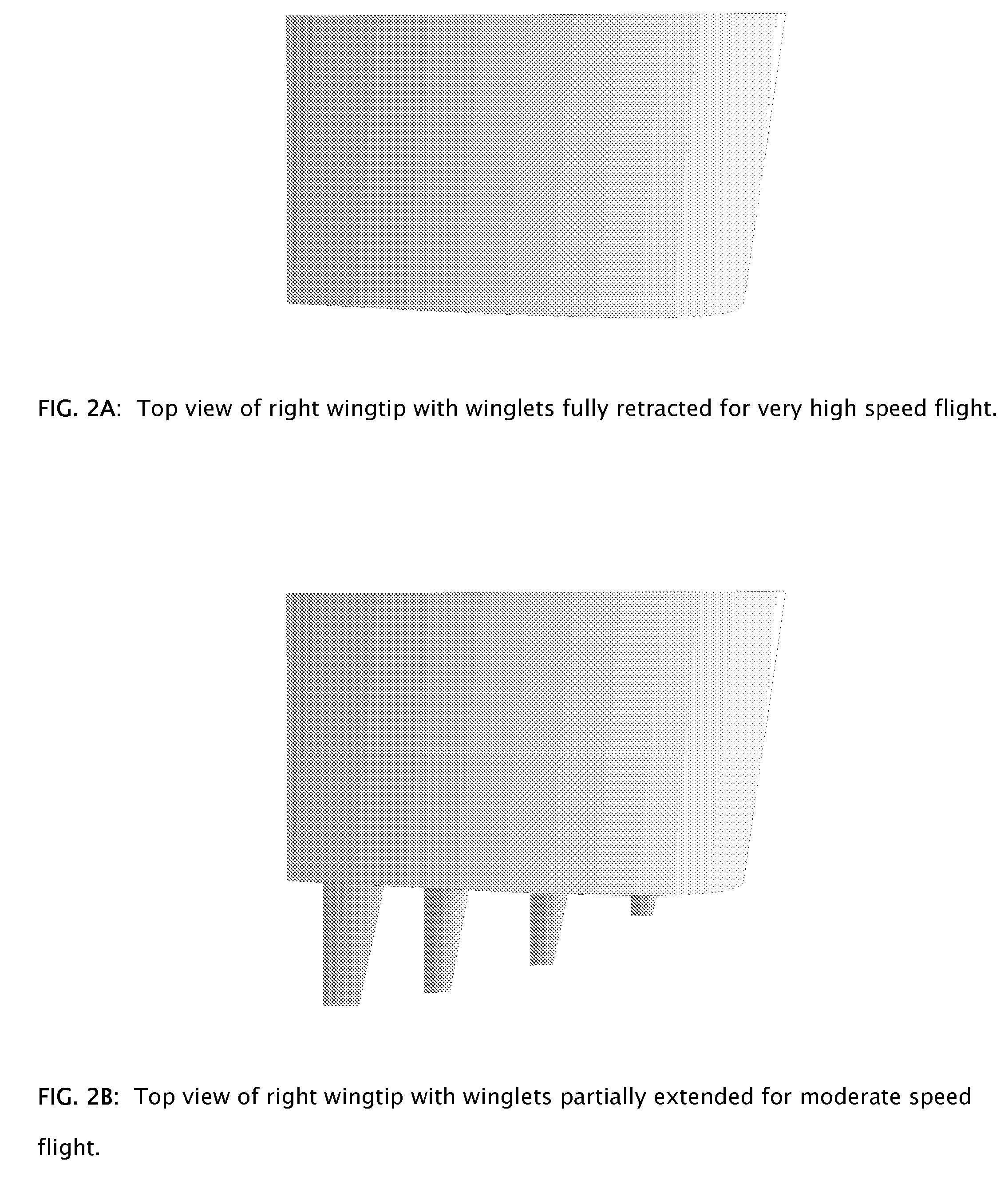
[0011] As illustrated in FIG. 1A, an airfoil that produces lift will have some high pressure air from the bottom of the wing escaping around the wingtip to the top of the wing. This creates a strong upwash immediately outboard of the wingtip as well as a powerful vortex at the trailing edge of the wingtip. FIG. 1B shows what happens when airfoils are placed in this upwash. Because the upwash is causing the local airflow to travel at an upward angle, the airfoils must be tilted forward (leading edge down) to meet the airflow at the proper angle. This will cause the resultant lift vector of the airfoils to be tilted forward and slightly into the direction of the relative wind (as illustrated). Not only will this create a lift component that will add to the overall lift of the wing, but it will also create a thrust component that will reduce the overall drag. This increase in lift and reduction in drag will significantly improve the lift to drag ratio at high angles of attack. In accor...


PUM


Abstract

Unlike conventional winglets that attempt to block out wingtip vortices, these winglets use multiple airfoils to recycle much of the energy of these vortices back into useful lift and thrust (drag reduction). This will improve the lift to drag ratio at high angles of attack. These airfoils extend outward in the plane of the wing from each wingtip and are specially shaped to make them easy to extend and retract. Not only can they function over a continuum of airspeeds and angles of attack, but they can also be fully retracted at very high speeds to avoid parasite drag penalties.

Description

BACKGROUND OF THE INVENTION [0001] One of the main problems for aircraft flying at low speeds is the increase in induced drag due to wingtip vortices. This induced drag is proportionate to the inverse of the velocity squared. This problem is traditionally alleviated by using fixed winglets but these can be a liability at high speeds because they increase the wetted area and thus increase the parasite drag. As a result, virtually all wing designs either present a compromise between high speed and low speed efficiency, or sacrifice one for the other. [0002] A device that can reduce the wingtip vortices at low speeds or high angles of attack while being able to retract for high speeds or low angles of attack would present distinct benefits. Additionally, if the degree of extension can be varied along a continuum throughout various airspeeds or angles of attack, that would be even more beneficial. BRIEF SUMMARY OF THE INVENTION [0003] Wingtip vortices are produced by high pressure air a...

Claims


Application Information

Patent Timeline
IPC IPC(8): B64C23/06
CPCY02T50/164B64C23/065B64C23/072B64C23/076Y02T50/10
Inventor GRANT, ROGER HUGH
Owner GRANT ROGER HUGH
Why Eureka
Try Eureka