Shielding device

a shielding device and shielding technology, applied in semiconductor devices, semiconductor/solid-state device details, electrical apparatus, etc., can solve problems such as inconvenient shielding, inability to and inability to decouple or shield critical circuit parts from the rest of the integrated circuit. achieve the effect of cost-effectiveness

Inactive Publication Date: 2007-11-15
INFINEON TECH AG
View PDF14 Cites 41 Cited by
  • Summary
  • Abstract
  • Description
  • Claims
  • Application Information

AI Technical Summary

Benefits of technology

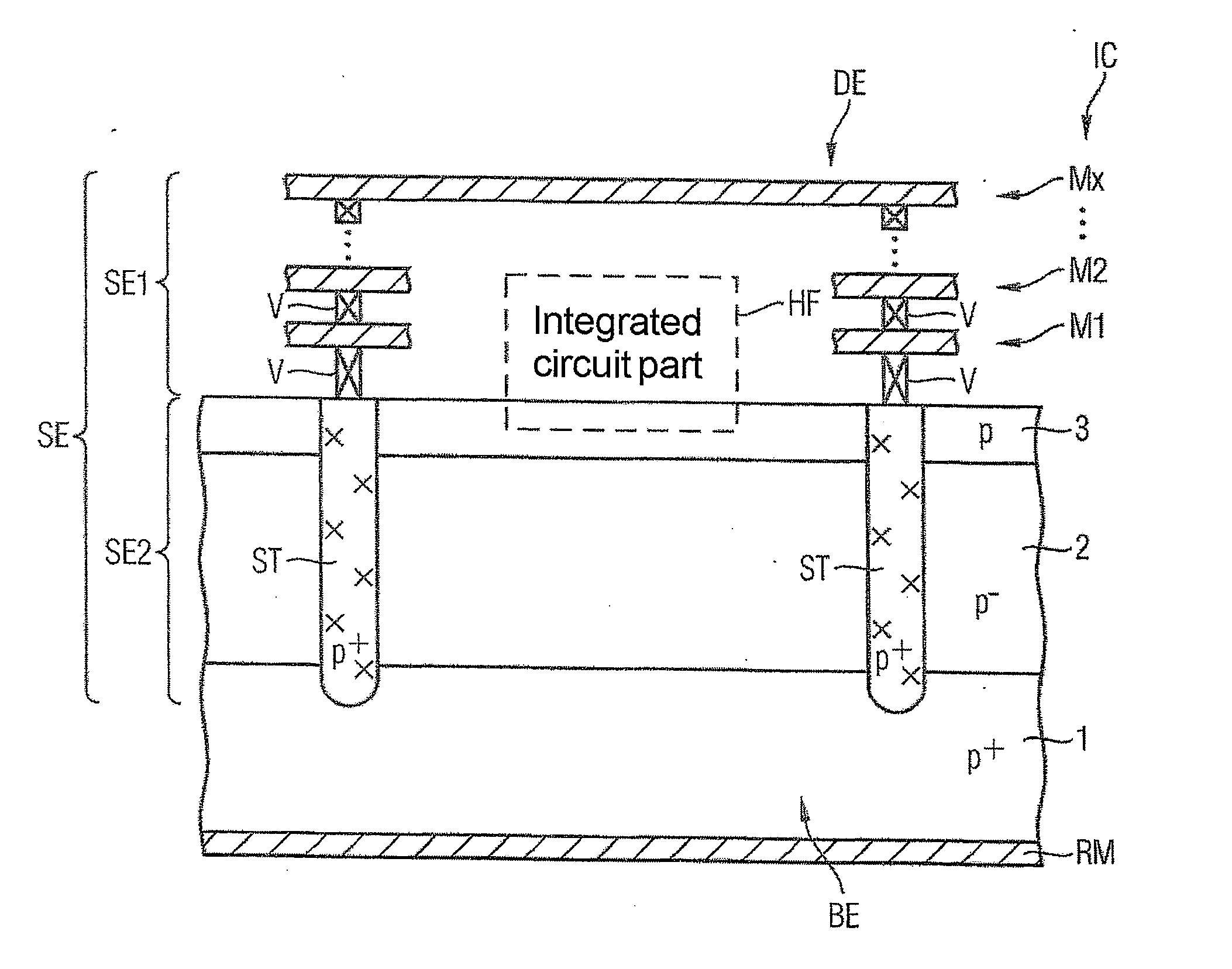
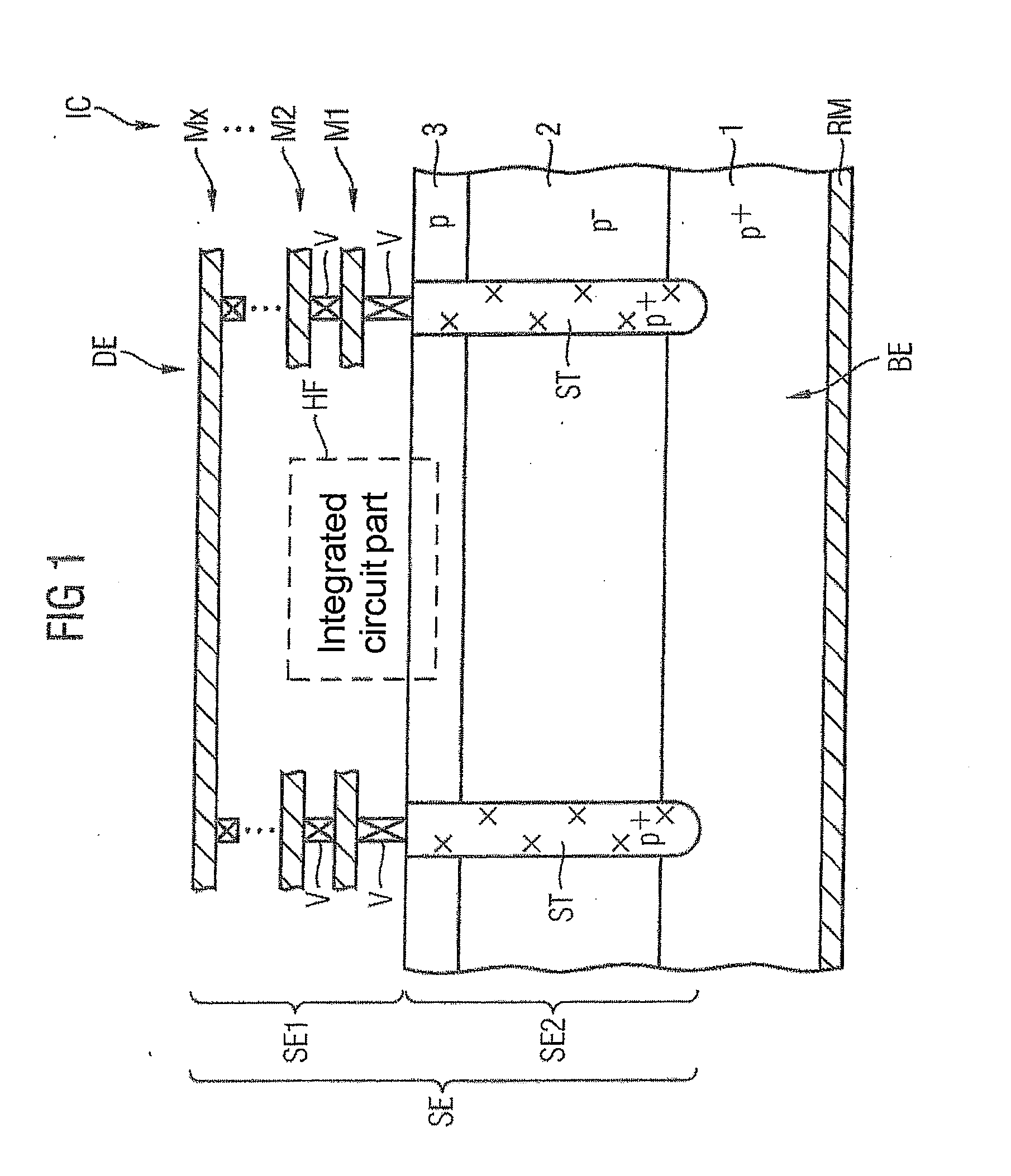
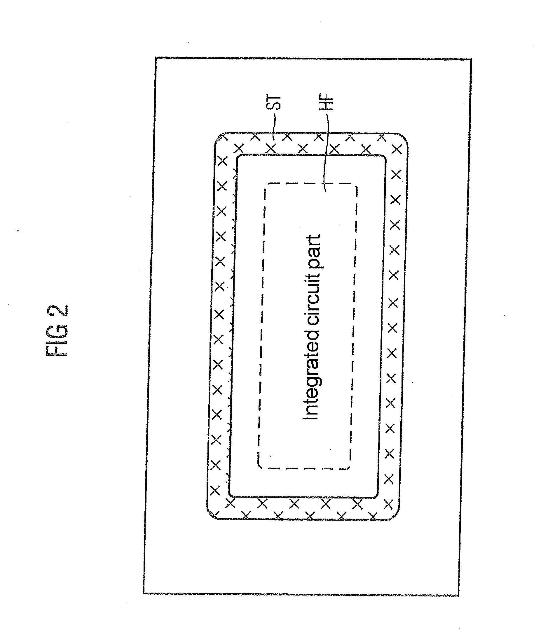
[0010] One embodiment includes a shielding device for shielding from electromagnetic radiation. The shielding device includes a shielding base element, a shielding cover element and a shielding lateral element for electrically connecting the base element to the cover element in such that a circuit part to be shielded is arranged within the shielding elements. Since at least one partial section of the shielding elements includes a semiconductor material, for the first time a shielding device can be realized completely and cost-effectively in an integrated circuit.

Problems solved by technology

In the realization of highly complex circuits, particularly in integrated semiconductor circuits, an increasingly wide variety of circuit parts or circuit blocks have to be realized, which often influence one another in an undesirable manner.
Particularly in the case of radiofrequency transformer circuits, such crosstalk often becomes apparent through undesirable emissions in the form of spurii, that is, secondary lines in the spectrum, or undesirable oscillation.
Such decoupling or shielding of critical circuit parts from the rest of an integrated circuit is at odds, however, with the increasing integration density demanded particularly in the case of integrated semiconductor circuits.
Although the principles for such a multichip module design and also the associated production technologies are relatively well known, such conventional technologies have been unable hitherto to enable a production method with low costs and a high volume.
An increased space requirement, which is an obstacle to the future increased integration density with its accompanying miniaturization, is disadvantageous in this case, however.
Since the attenuation of the electromagnetic fields increases with distance, severe limits are imposed on more extensive integration.

Method used


Image

  • Shielding device
  • Shielding device
  • Shielding device

Examples


Embodiment Construction

[0019] In the following Detailed Description, reference is made to the accompanying drawings, which form a part hereof, and in which is illustrated by way of illustration specific embodiments in which the invention may be practiced. In this regard, directional terminology, such as “top,”“bottom,”“front,”“back,”“leading,”“trailing,” etc., is used with reference to the orientation of the Figure(s) being described. Because components of embodiments of the present invention can be positioned in a number of different orientations, the directional terminology is used for purposes of illustration and is in no way limiting. It is to be understood that other embodiments may be utilized and structural or logical changes may be made without departing from the scope of the present invention. The following detailed description, therefore, is not to be taken in a limiting sense, and the scope of the present invention is defined by the appended claims.

[0020] One embodiment provides a shielding de...


PUM


Abstract

One aspect of the invention relates to a shielding device for shielding from electromagnetic radiation, including a shielding base element, a shielding cover element and a shielding lateral element for electrically connecting the base element to the cover element in such that a circuit part to be shielded is arranged within the shielding elements. Since at least one partial section of the shielding elements includes a semiconductor material, a shielding device can be realized completely and cost-effectively in an integrated circuit.

Description

CROSS-REFERENCE TO RELATED APPLICATIONS [0001] This Utility Patent Application claims the benefit of the filing date of German Application No. DE 10 2006 022 360.8, filed May 12, 2006, which is herein incorporated by reference. BACKGROUND [0002] One aspect of the invention relates to a shielding device for shielding from electromagnetic radiation, and in particular to an integrated shielding device for shielding from electromagnetic radiation for circuit parts of an integrated semiconductor circuit which are to be shielded. [0003] In the realization of highly complex circuits, particularly in integrated semiconductor circuits, an increasingly wide variety of circuit parts or circuit blocks have to be realized, which often influence one another in an undesirable manner. Logic circuit parts may be involved in this case, for example, which cause a crosstalk in the form of coupling of electromagnetic fields into analog circuit parts, for example. [0004] Particularly in the case of radio...

Claims


Application Information

Patent Timeline
Patent Type & Authority Applications(United States)
IPC IPC(8): H01L23/552
CPCH01L23/5225H01L23/552H01L23/60H01L2924/0002H01L2924/00
Inventor BAKALSKI, WINFRIEDEISENER, BERNDSEIDEL, UWEZANNOTH, MARKUS
Owner INFINEON TECH AG
Why Eureka
Try Eureka