Electrode-foil interface structure

a technology of electrodes and foils, applied in the manufacture of electrode systems, cold cathode manufacturing, electric discharge tubes/lamps, etc., can solve the problems of foil overheating in the foil area, lamp failure risk in the region, and the tendency of failure to occur in the sealing region, so as to reduce the thickness and reduce the thickness

Inactive Publication Date: 2007-11-15
GENERAL ELECTRIC CO
View PDF7 Cites 4 Cited by
  • Summary
  • Abstract
  • Description
  • Claims
  • Application Information

AI Technical Summary

Benefits of technology

[0004] In another aspect, a lamp includes an envelope. At least one interior electrode is provided for generating light within the envelope during operation of the lamp. The interior electrode includes a shank portion and terminates in a shelf. A region of progressively decreasing thickness extends between the shank portion and the shelf. The lamp further includes an exterior connector and a foil connector which electrically connects the exterior connector with the interior electrode, the foil connector being mounted to the shelf.
[0005] In another aspect, a method of forming a foil interface includes providing a first electrically conductive connector comprising a shank portion and terminating in a shelf, a region of progressively decreasing thickness extending between the shank portion and the shelf. An electrically conductive foil connector is mounted to the shelf adjacent a first end of the foil connector.

Problems solved by technology

In particular, it relates to an interface structure which decreases the risk of lamp failure in the region of the foil.
However, there remains a tendency for failures to occur in the region of the seal.
Such failures tend to occur where the voltage to the lamp is not properly regulated, leading to overheating in the foil area.
For example, the seal can crack open, which results in lamp failure.
Some of the failures are thought to be due to oxidation reaction of the molybdenum foil.
These passageways permit oxygen or dose material to enter the foil area of the lamp seal and oxidize the foil, leading to overheating and cracking of the seal.

Method used


Image

  • Electrode-foil interface structure
  • Electrode-foil interface structure
  • Electrode-foil interface structure

Examples


Embodiment Construction

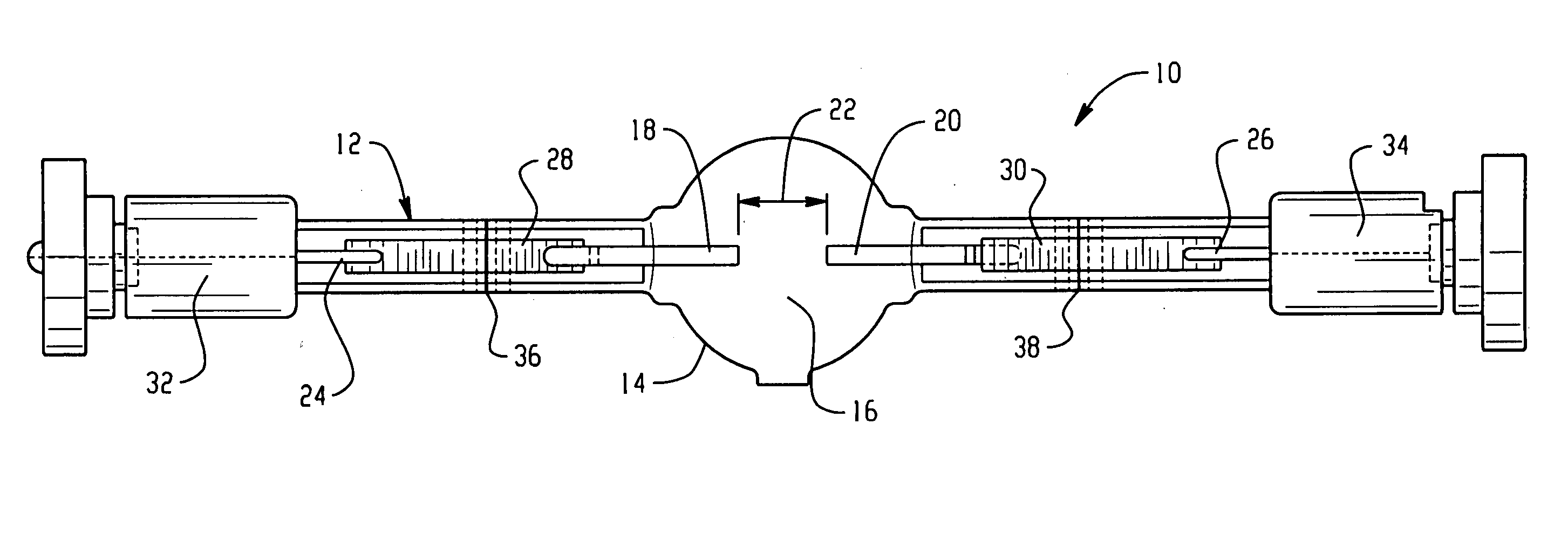
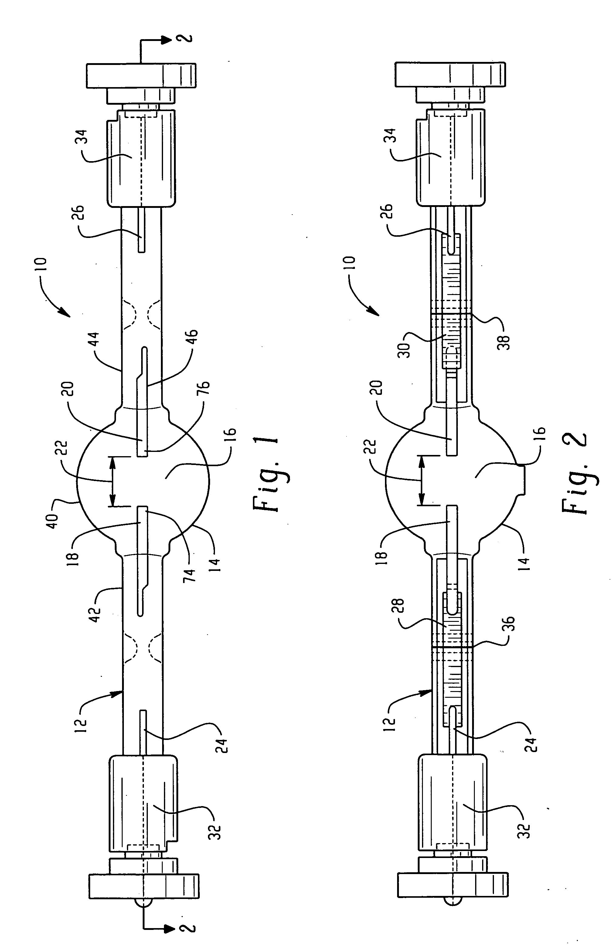
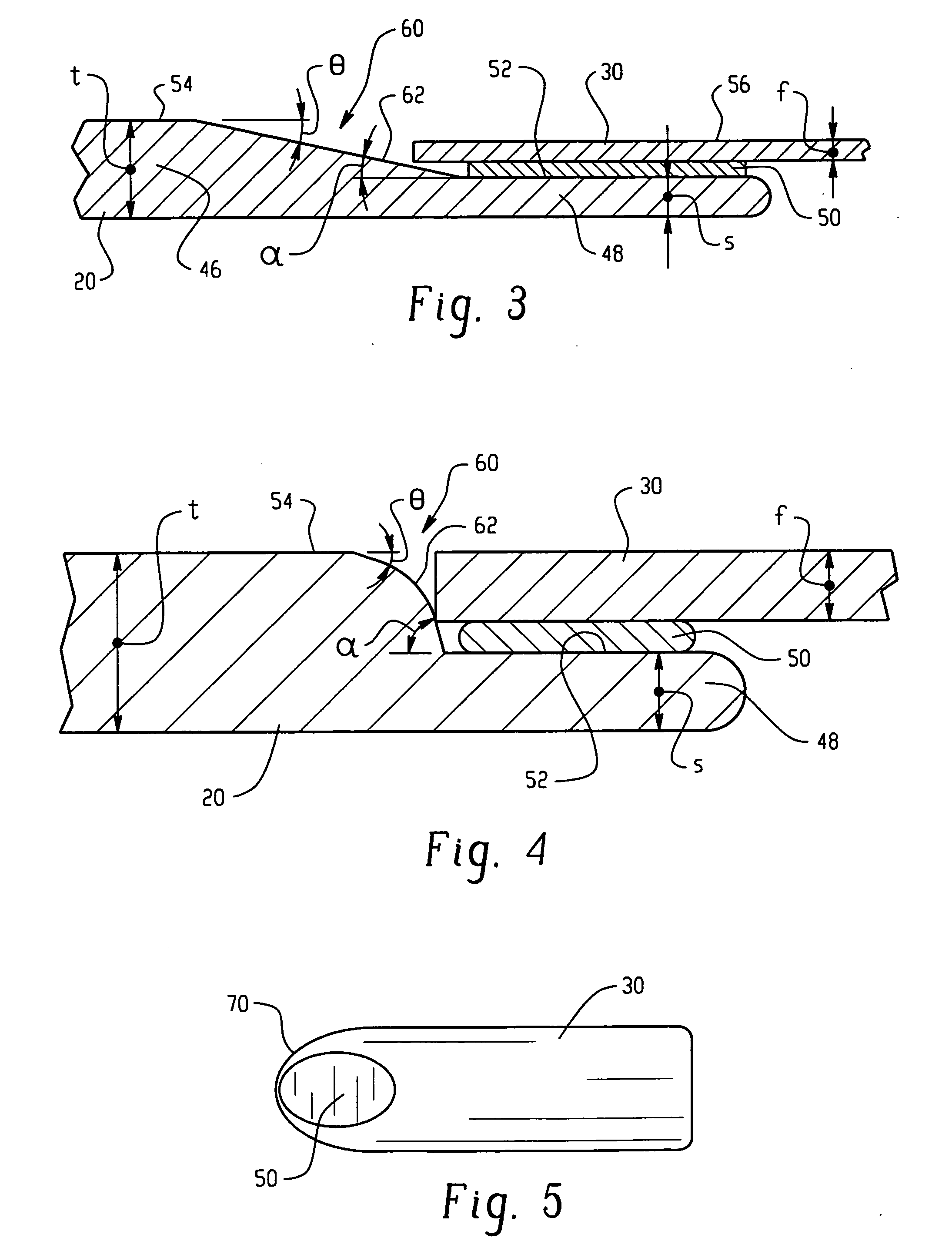
[0012] Aspects of the exemplary embodiment relate to systems and methods for reducing the failure of lamps due to lamp stem rupture. It is now proposed that one of the failure modes in the region of the pinch seal is due to stress risers. In a conventional molybdenum foil interface, the electrode and outer connector, which are electrically connected by the foil, are substantially thicker than the foil. It is proposed that the sharp corners created at the foil interface place stresses on the vitreous material in the region of the pinch seal and contribute to lamp failure. In the exemplary embodiment, a foil interface structure is designed to reduce these stress risers and thereby provide a lamp which is less prone to failure. As a result, the life of hermetic seals around the molybdenum foil and electric lamps employing such seals can be increased.

[0013] In various aspects, the interface is formed between an electrically conductive foil connector, such as a molybdenum-containing foi...


PUM


Abstract

A foil interface suited to interconnection of an electrode (18, 20) with an outer connector (24, 26) of a lamp includes a first electrically conductive connector (18, 20, 24, 26) includes a shank portion (46) and terminating in a shelf (48). A region (60) of progressively decreasing thickness is intermediate the shank portion and the shelf. An electrically conductive foil connector (28, 30) is mounted to the shelf adjacent a first end (70) of the foil connector.

Description

BACKGROUND OF THE INVENTION [0001] The invention relates generally to electric lamps formed with a pinched seal or shrink seal, in which a molybdenum foil is incorporated in the pinch. In particular, it relates to an interface structure which decreases the risk of lamp failure in the region of the foil. [0002] Electric lamps having a quartz glass lamp envelope frequently have outer current conductors of molybdenum which are connected to internal electrodes by a molybdenum foil. The foil is used in the area of the pinch seal. Being more flexible than the thicker molybdenum conductor, it is better able to absorb the stresses placed on the conductor in the seal area. However, there remains a tendency for failures to occur in the region of the seal. Such failures tend to occur where the voltage to the lamp is not properly regulated, leading to overheating in the foil area. For example, the seal can crack open, which results in lamp failure. Some of the failures are thought to be due to ...

Claims


Application Information

Patent Timeline
Patent Type & Authority Applications(United States)
IPC IPC(8): H01J61/30H01J17/16
CPCH01J9/28H01K1/40H01J61/368H01J61/36
Inventor AURONGZEB, DEEDER M.GIORDANO, ROCCO T.SIVARAMAN, KARTHIK
Owner GENERAL ELECTRIC CO
Why Eureka
Try Eureka