Method and Apparatus for Cooling Electronics with a Coolant at a Subambient Pressure

a technology of subambient pressure and cooling electronics, applied in the field of cooling techniques, can solve the problems of large amount of power consumption, large amount of heat produced, and large size of suitable refrigeration units

Active Publication Date: 2007-11-15
RAYTHEON CO
View PDF99 Cites 55 Cited by
  • Summary
  • Abstract
  • Description
  • Claims
  • Application Information

AI Technical Summary

Benefits of technology

[0005] Some embodiments of the invention may provide numerous technical advantages. Other embodiments may realize some, none, or all of these advantages. For example, according to one embodiment, large amounts of heat may be removed from a heat-generating structure, allowing, for example, more densely-packed electronics to be utilized.

Problems solved by technology

In contrast, there are other circuits which consume large amounts of power, and produce large amounts of heat.
However, suitable refrigeration units are large, heavy, and consume many kilowatts of power in order to provide adequate cooling.
Although refrigeration units of this type have been generally adequate for their intended purposes, they have not been satisfactory in all respects.
An equally important factor is the inability of existing methods to remove high flux heat loads from electronic components and modules.
Existing approaches, which use a coolant flowing inside a coldplate or thermal plane to which electrical components and modules are mounted, have inadequate heat transfer performance to meet future needs.
In addition, approaches using two-phase, sprayed fluorinerts are not satisfactory in all respects.

Method used


Image

  • Method and Apparatus for Cooling Electronics with a Coolant at a Subambient Pressure
  • Method and Apparatus for Cooling Electronics with a Coolant at a Subambient Pressure
  • Method and Apparatus for Cooling Electronics with a Coolant at a Subambient Pressure

Examples


Embodiment Construction

[0015] Example embodiments of the present invention and their advantages are best understood by referring to FIGS. 1A-4B of the drawings, like numerals being used for like and corresponding parts of the various drawings.

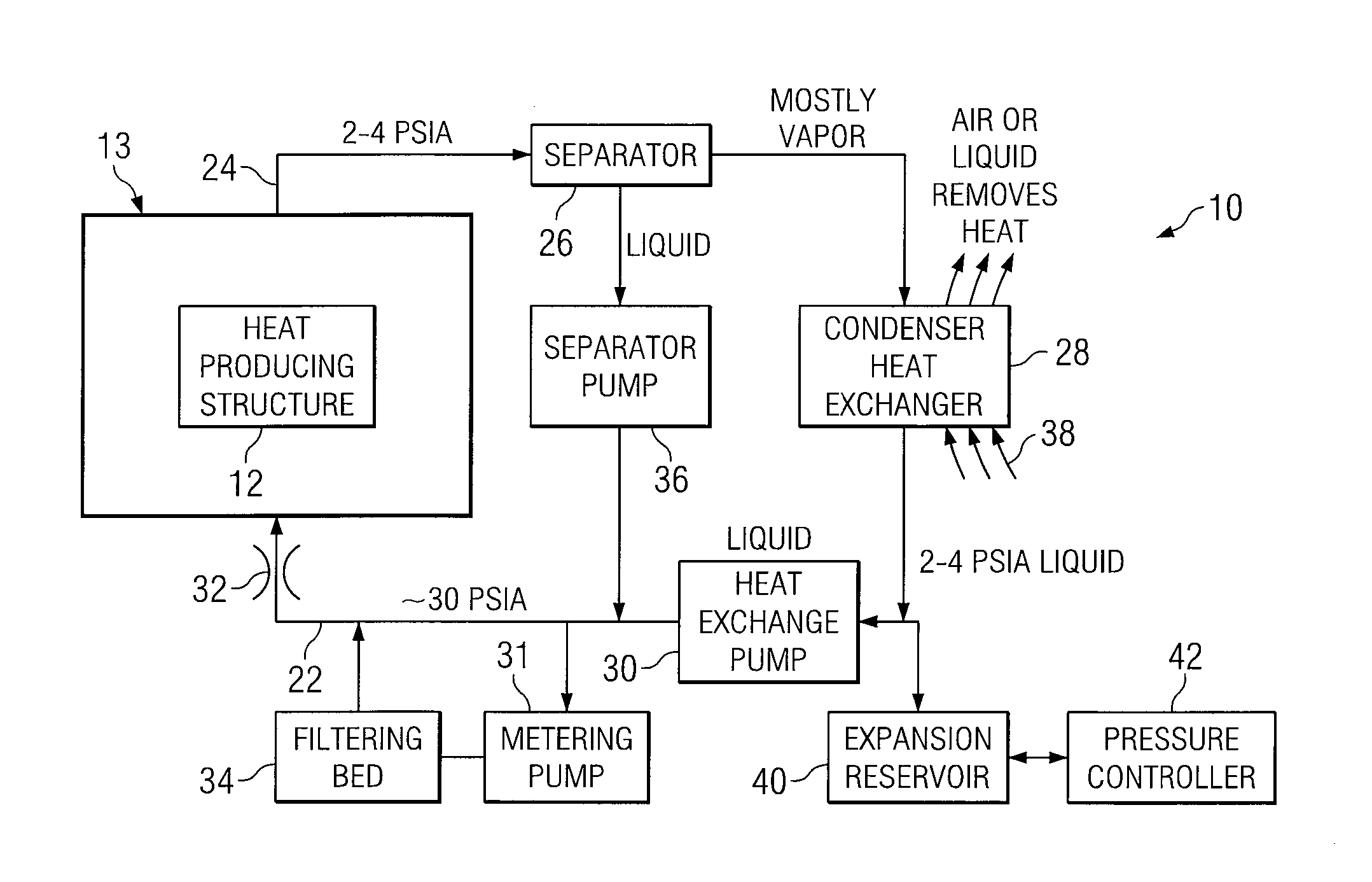
[0016]FIG. 1A is a block diagram of an apparatus 10 that includes a heat-generating structure 12. The heat-generating structure 12 may be, in a particular embodiment, one or more microelectronic assemblies, which may produce an enormous amount of heat that is difficult to cool using conventional techniques. Alternatively, heat-generating structures may include no electronics and / or may not produce excessive amounts of heat. In general, although the teachings of the invention may provide greater benefit to cooling microelectronics that produce excessive amounts of heat, these teachings are applicable to cooling any type of device at high or lower levels of heat-generation. According to the teachings of one embodiment of the invention, heat-generating structure 12 is ...
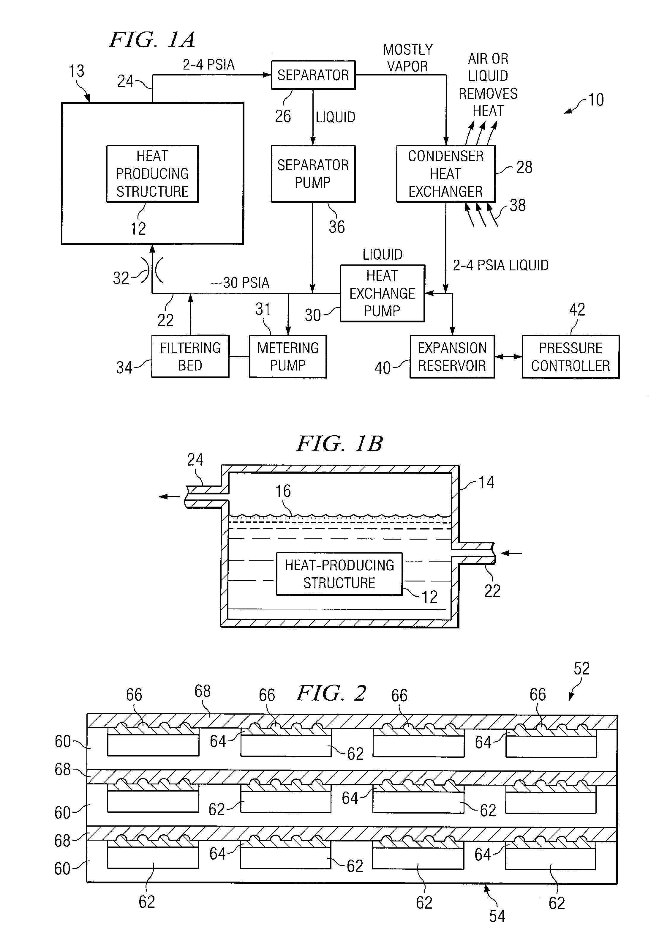

PUM


Abstract

According to one embodiment of the invention, a method is provided for cooling heat-generating structure disposed in an environment having an ambient pressure. The heat-generating structure includes electronics. The method includes providing a coolant, reducing a pressure of the coolant to a subambient pressure at which the coolant has a boiling temperature less than a temperature of the heat-generating structure, and bringing the heat-generating structure and the coolant at the subambient pressure into contact with one another, so that the coolant boils and vaporizes to thereby absorb heat from the heat-generating structure. In a more particular embodiment the coolant is either pure water or pure methanol with an electrical resistivity level of greater than one million Ohms-cm. Further, in another particular embodiment the method includes filtering the coolant to maintain its purity above a particular level.

Description

TECHNICAL FIELD OF THE INVENTION [0001] This invention relates in general to cooling techniques and, more particularly, to a method and apparatus for cooling electronics with a coolant at a subambient pressure. BACKGROUND OF THE INVENTION [0002] Some types of electronic circuits use relatively little power, and produce little heat. Circuits of this type can usually be cooled satisfactorily through a passive approach, such as convection cooling. In contrast, there are other circuits which consume large amounts of power, and produce large amounts of heat. One example is the circuitry used in a phased array antenna system. Others include other types of electronics, such as densely packed electronics used for current and future computational circuits, which can produce 1000-10,000 watts of heat per cubic centimeter, or more. [0003] In the modern phased array antenna example, the system can easily produce 25 to 500 kilowatts of heat, or even more. Future computers are envisioned to produ...

Claims


Application Information

Patent Timeline
Patent Type & Authority Applications(United States)
IPC IPC(8): H05K7/20
CPCF25B23/006F25B43/00F28D15/0266F28D2021/0031F28F23/00H01L2924/0002H01Q1/02H01L2924/00
Inventor WEBER, RICHARD M.WYATT, WILLIAM G.RUMMEL, KERRIN A.
Owner RAYTHEON CO
Why Eureka
Try Eureka