Two terminals quasi resonant tank circuit

a resonant tank and terminal technology, applied in the field of resonant circuits, can solve the problems of increasing the stress of switching and component losses, increasing electromagnetic interference (emi), noise and switching commutation problems, and limited use in commercial applications

Active Publication Date: 2007-11-15
MYPAQ HLDG LTD
View PDF54 Cites 104 Cited by
  • Summary
  • Abstract
  • Description
  • Claims
  • Application Information

AI Technical Summary

Benefits of technology

[0018] It is an object of the invention to provide substantially Zero Voltage Switching (ZVS) for the primary switch. It is a further object of the invention to provide substantially Zero Voltage Switching for the auxiliary switch. It is another object of the invention to include the energy stored in most parasitic capacitances in the primary switch, the secondary switch and the ...

Problems solved by technology

However, an increase in switching frequency can cause a corresponding increase in switching and component stress related losses, as well as increased electromagnetic interference (EMI), noise, and switching commutation problems, due to the rapid ON/OFF switching of the semiconductor switches at high voltage and/or high current levels.
However, the complexity required to provide control to the power switches (illustrated below as S1 and S2), and the components associated with complex control, create a limited use in commercial applications.
A drawback to use of the flyback is the relatively high voltage and current stress suffered by the switching components.
This parasitic oscillation is extremely rich in harmonics and pollutes the ...

Method used


Image

  • Two terminals quasi resonant tank circuit
  • Two terminals quasi resonant tank circuit
  • Two terminals quasi resonant tank circuit

Examples


Embodiment Construction

[0027] In the following description, numerous details and alternatives are set forth for purpose of explanation. However, one of ordinary skill in the art will realize that the invention can be practiced without the use of these specific details. In other instances, well-known structures and devices are shown in block diagram form to not obscure the description of the invention with unnecessary detail.

[0028] A detailed description of the principles of operation will be given based on the preferred embodiment of the invention in a power converter of the Quasi Resonant Flyback type. The invention can also be used on other converter types such as, but not limited to, a forward converter.

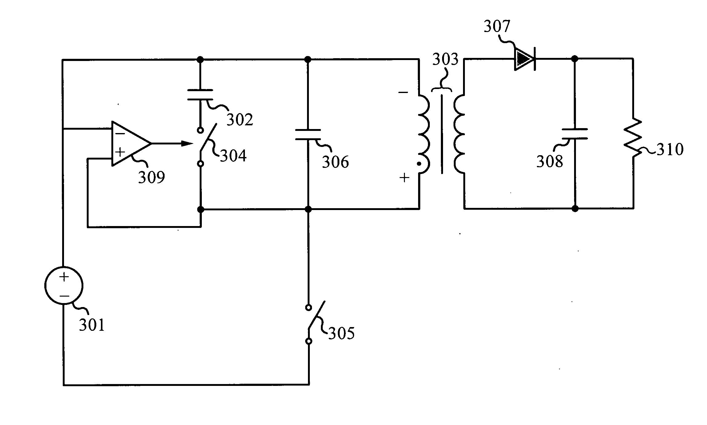
[0029] The circuit of FIG. 3 illustrates a conceptual representation of the invention in a Quasi Resonant Flyback converter. The power converter in FIG. 3 comprises of a transformer (303) with primary and secondary windings, a primary switch (305), an auxiliary switch (304), a first resonance capacito...


PUM


Abstract

A power converter includes a transformer, a primary switch, an auxiliary switch, first and second resonance capacitors, and a secondary side rectification means. A switch mode power supply is formed to use reflected voltage and parasitic capacitance as an energy source for a transformer resonance. The auxiliary switch effectively exchanges energy between the primary inductance of the transformer and the first and second resonant capacitors. The auxiliary switch effectively switches the transformer resonance between two distinct frequencies. In one embodiment of the invention, the power converter can be, but is not limited to, a flyback converter and further includes a comparator and a driver. The comparator is for detecting the voltage across the second resonance capacitor and the driver is configured to drive the auxiliary switch based on the output state of the comparator. The resonant nature of the converter provides zero voltage (ZVS) for the primary switch as well as for the auxiliary switch.

Description

RELATED APPLICATIONS [0001] This application claims benefit of priority under 35 U.S.C. section 119(e) of the U.S. Provisional Patent Application filed Feb. 14, 2006, entitled “TWO TERMINALS QUASI RESONANT TANK CIRCUIT.”FIELD OF THE INVENTION [0002] The present invention is generally directed to the field of resonant circuits. More specifically, the present invention is directed to two terminals quasi resonant tank circuit. BACKGROUND OF THE INVENTION [0003] There are several power converter topologies that have been developed over the years, which are intended to improve the power density and switching efficiency of power converters. An emerging focus of new converter topologies is to provide a means to reduce or eliminate converter switching losses, while increasing the switching frequencies. Lower loss and higher switching frequency means more efficient converters, which can reduce the size and weight of converter components. Additionally, with the introduction of high speed comp...

Claims


Application Information

Patent Timeline
IPC IPC(8): H02M3/335
CPCY02B70/1433H02M3/33507H02M3/33523Y02B70/10H02M3/33571H02M3/01
Inventor JANSEN, ARIANTELEFUS, MARKSHARIFIPOUR, BAHMAR
Owner MYPAQ HLDG LTD
Why Eureka
Try Eureka