Viscous Fluid Transferring Device

a fluid transfer device and fluid technology, applied in liquid handling, transportation and packaging, packaging goods types, etc., can solve the problems of increasing the cost of air removal and the capacity decrease, and achieve the effect of increasing the cost of transfer, increasing the operating time of the evacuating mechanism, and increasing the cost of electricity for operating the evacuating mechanism

Inactive Publication Date: 2007-11-22
KIKKOMAN CORP
View PDF3 Cites 0 Cited by
  • Summary
  • Abstract
  • Description
  • Claims
  • Application Information

AI Technical Summary

Benefits of technology

[0018] In the invention defined in claim 2, the evacuation control part starts the evacuating mechanism when the flow rate of the viscous fluid measured with a flowmeter provided in the transfer pipe has fallen sharply.
[0019] In the invention defined in claim 3, the evacuation control part starts the evacuating mechanism when the time from the start of operation of the pump has reached a preset time.
[0022] In the invention defined in claim 1, by the pump mechanism being operated alone for a while from the start of the transfer and both the evacuating mechanism and the pump mechanism being operated in a last period of the transfer, it is possible to transfer viscous fluid in the flow passages of the transfer apparatus without leaving any behind. This is realized just by providing a branch pipe, an extension pipe, an evacuating mechanism and an evacuation control part in addition to a storage tank, a transfer pipe and a pump mechanism of related art.
[0023] The branch pipe and the extension pipe are simple pipes, the evacuating mechanism can be a cheap vacuum pump, and the evacuation control part can be a general-purpose controller; consequently, it is possible to transfer a viscous fluid in a storage tank to a mash tub or the like without leaving any behind with the addition of only a small-scale mechanism.
[0025] If the evacuating mechanism is started by a timer, it starts before the time at which it becomes necessary, the operating time of the evacuating mechanism becomes long, the cost of the electricity for operating the evacuating mechanism increases, and the cost of the transfer increases.
[0026] On this point, in the claim 2 invention, because the evacuating mechanism is started at the time at which it becomes necessary, the operating time of the evacuating mechanism becomes short, the cost of the electricity for operating the evacuating mechanism can be reduced, and the cost of the transfer can be compressed.

Problems solved by technology

However, when the bottom part is made a cone part, its capacity decreases.
And, when a mash is considered in place of the slurry 126, because large quantities of air mix in with the mash, from the need to suppress changes in the quality of the mash it is necessary for the air to be removed as quickly as possible, and the cost of air removal also mounts up.

Method used


Image

  • Viscous Fluid Transferring Device
  • Viscous Fluid Transferring Device
  • Viscous Fluid Transferring Device

Examples


Embodiment Construction

[0032] A best mode for carrying out the invention will now be described on the basis of the accompanying drawings. The drawings are to be viewed in the orientation of the reference numbers.

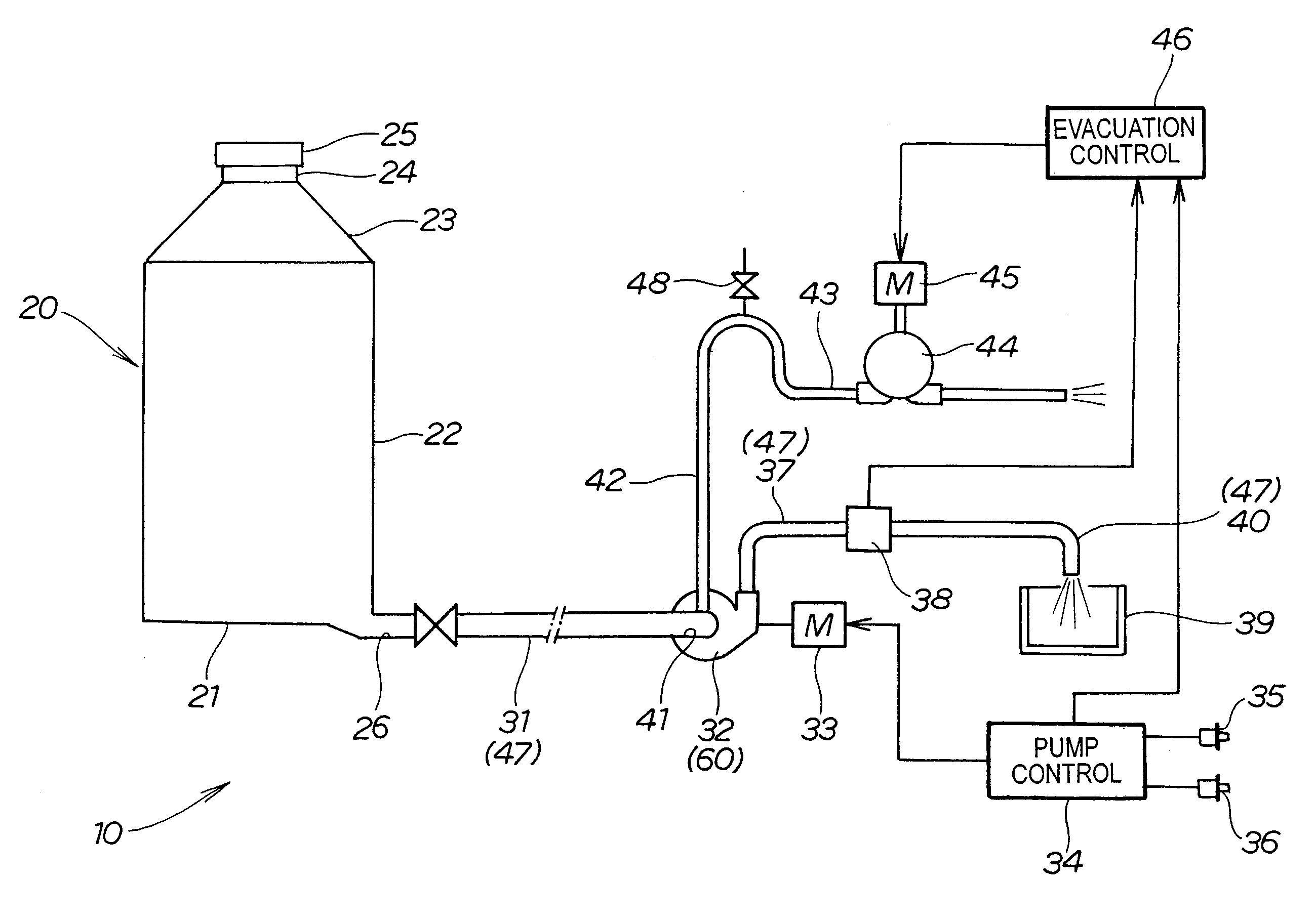
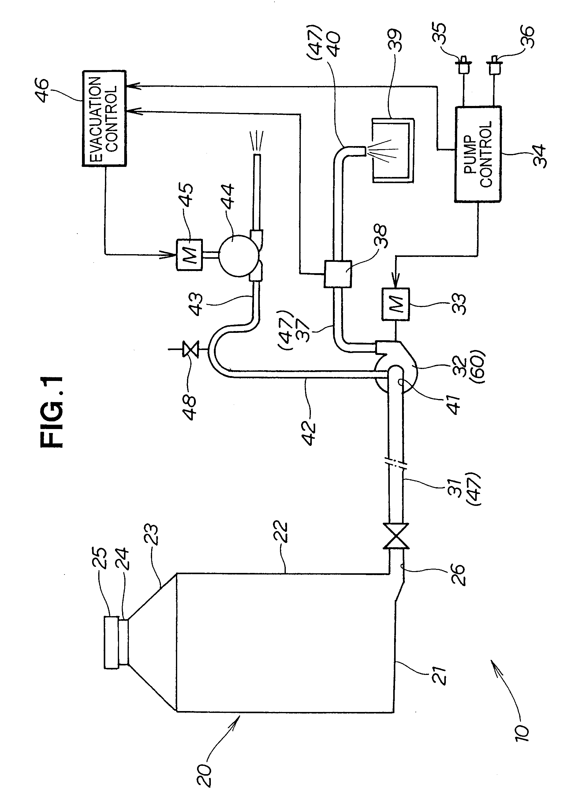
[0033]FIG. 1 is a basic construction view of a transfer apparatus for a viscous fluid, according to the invention.

[0034] A transfer apparatus 10 for a mash constituting a viscous fluid is made up of a storage tank 20 for storing mash; a first transfer pipe 31, extending from the bottom of the storage tank 20, for taking mash out; a pump mechanism 32 connected to this first transfer pipe 31; a motor 33 for driving this pump mechanism; a pump control part 34 for controlling the pump mechanism 32 by operating / stopping the motor 33; a pump Start button 35 and a pump Stop button 36 connected to the pump control part 34; a second transfer pipe 37 extending from the pump mechanism 32; a flowmeter 38 connected to this second transfer pipe 37; a third transfer pipe 40 extending from this flowmeter 38 to ...


PUM

PropertyMeasurementUnit
elevation angleaaaaaaaaaa
viscousaaaaaaaaaa

Abstract

A transfer apparatus with which it is possible to transfer a mash in a storage tank to a mash tub without leaving any mash in the tank and with the addition of only a small-scale mechanism. In a viscous fluid transfer apparatus of related art made up of a storage tank (20) for storing a viscous fluid; a transfer pipe (31) for taking out the viscous fluid, extending from the bottom of the storage tank; and a pump mechanism (32) disposed in the transfer pipe (31), on the intake port (41) side of the pump mechanism the invention additionally provides a branch pipe (42) branching upward from the transfer pipe (31), an extension pipe (43), an evacuating mechanism (44) and an evacuation control part (46). For a while after the start of a transfer, the transfer is carried out with the pump mechanism (32) only. Then, in a last period of the transfer, the evacuating mechanism (44) is started and the viscous fluid remaining at the bottom of the storage tank (20) is forcibly transferred to the intake port (41) of the pump mechanism by the sucking action of this evacuating mechanism (44). As a result, the pump mechanism (32) can transfer the viscous fluid without leaving any behind. The branch pipe branching upward from the transfer pipe and the extension pipe are simple pipes, the evacuating mechanism can be made a cheap vacuum pump, and the evacuation control part can be a general-purpose controller. Therefore, it is possible to transfer a viscous fluid in a storage tank to a mash tub or the like without leaving any in the tank, with the addition of only a small-scale mechanism.

Description

TECHNICAL FIELD [0001] This invention relates to a transfer apparatus for transferring a viscous fluid such as a soy sauce moromi or mash. BACKGROUND ART [0002] As an example of a viscous fluid, a soy sauce mash will be used in the following description. [0003]FIG. 8 hereof illustrates the principle of a conventional soy sauce mash transfer apparatus. A storage tank 101 for preparing, fermenting and maturing a soy sauce moromi or mash (hereinafter called “mash”) 100 is a large vessel made up of a bottom part 102 given a gradient; a cylindrical part 103 rising from the rim of this bottom part 102; a cone part 104 connected to the top of this cylindrical part 103; a feed opening 105 connected to a small-diameter top part of the cone part 104; and a cover 106, and has an outlet 107 in a corner of the bottom part 102. [0004] If the bottom part of the storage tank 101 is also made a cone part, it is possible to take out mash without any stagnating. However, when the bottom part is made a...

Claims


Application Information

Patent Timeline
Patent Type & Authority Applications(United States)
IPC IPC(8): B65B57/06A23L27/50
CPCF17D1/14
Inventor MATSUMOTO, KIYOSHISOMEYA, HIDEYUKIOURA, MASAMI
Owner KIKKOMAN CORP
Why Eureka
Try Eureka