Wheel hub drive for industrial trucks

a technology of industrial trucks and hub drives, which is applied in the direction of power driven steering, braking systems, lifting devices, etc., can solve the problem of normally extremely limited construction spa

Active Publication Date: 2007-11-22
JUNGHEINRICH AG
View PDF41 Cites 18 Cited by
  • Summary
  • Abstract
  • Description
  • Claims
  • Application Information

AI Technical Summary

Benefits of technology

[0015]When being applied to a steered wheel, it is advantageous according to a further embodiment of the present invention that drive gear system, drive motor and brake a

Problems solved by technology

The space for construction is normally extremely l

Method used


Image

  • Wheel hub drive for industrial trucks
  • Wheel hub drive for industrial trucks
  • Wheel hub drive for industrial trucks

Examples


Embodiment Construction

[0028]While this invention may be embodied in many different forms, there are described in detail herein a specific preferred embodiment of the invention. This description is an exemplification of the principles of the invention and is not intended to limit the invention to the particular embodiment illustrated

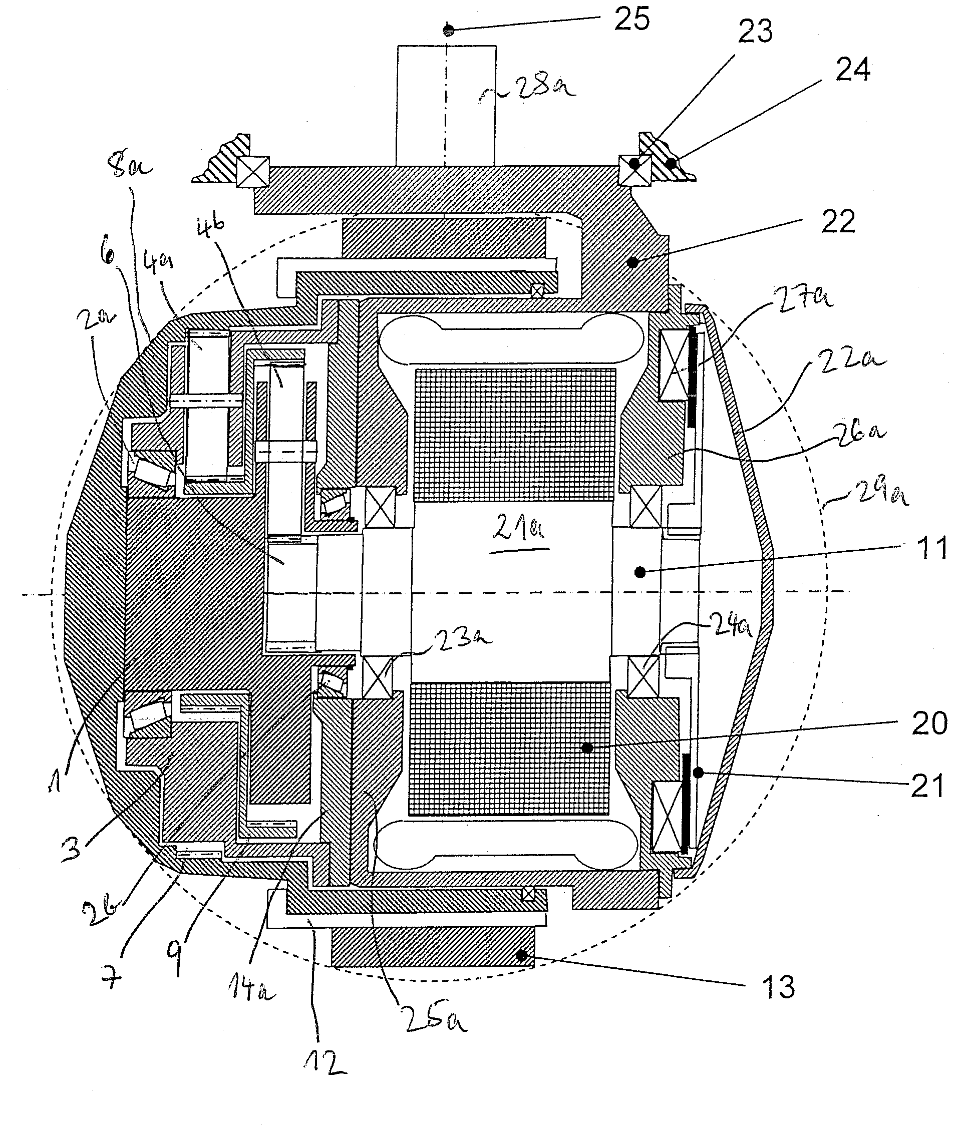
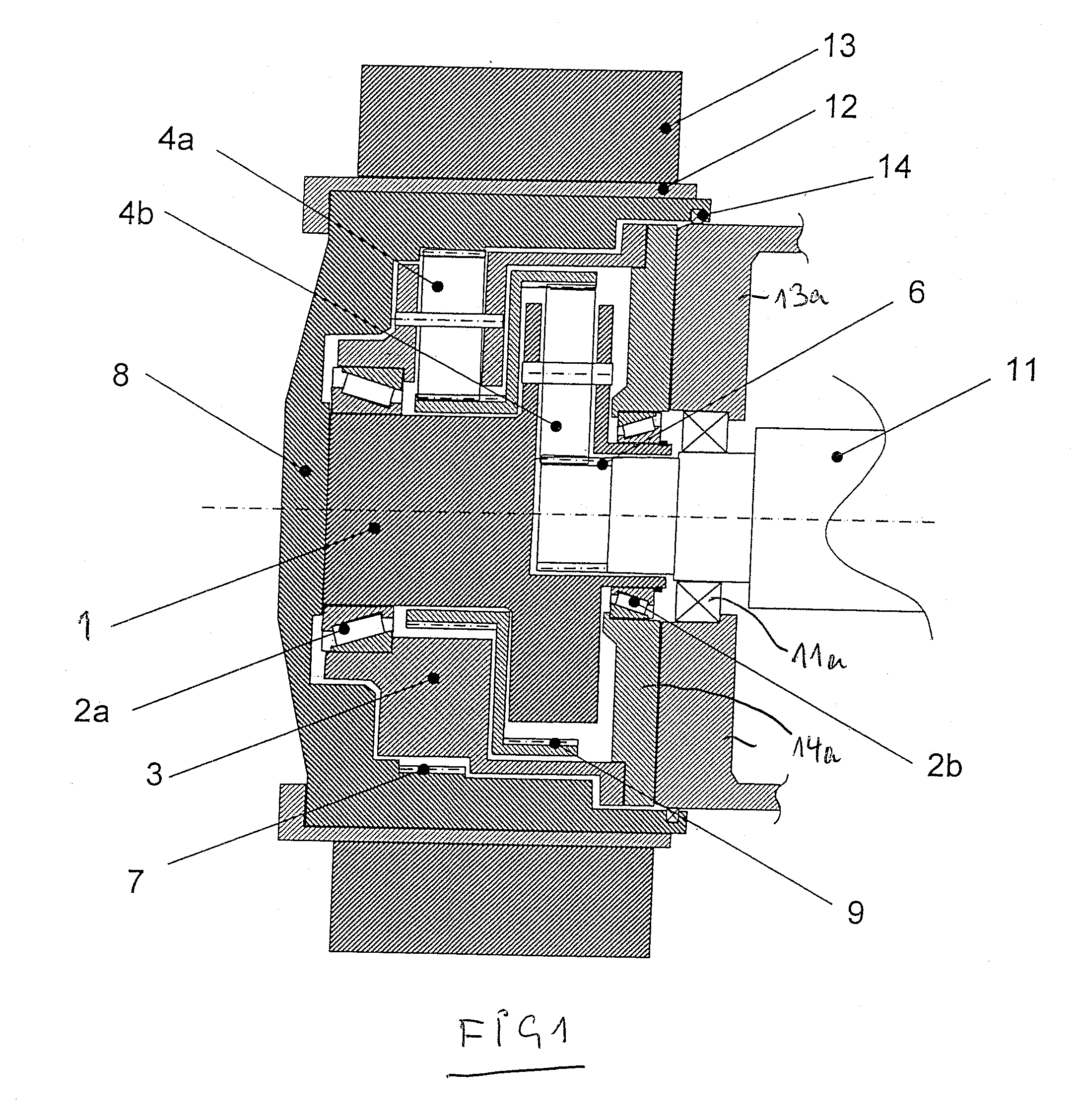
[0029]In FIG. 1, a tire 13 sits on a wheel rim 12. The shown wheel is a driven wheel of an industrial truck for instance, a four wheel fork lifter for example. It is driven by a not shown drive motor, which can be an electric or an hydraulic motor, via a drive shaft 11. The drive shaft 11 is rotatably mounted in a frame portion 13a of the industrial truck via a bearing 11a. A shield 14a is fixedly connected with the frame portion 13a.

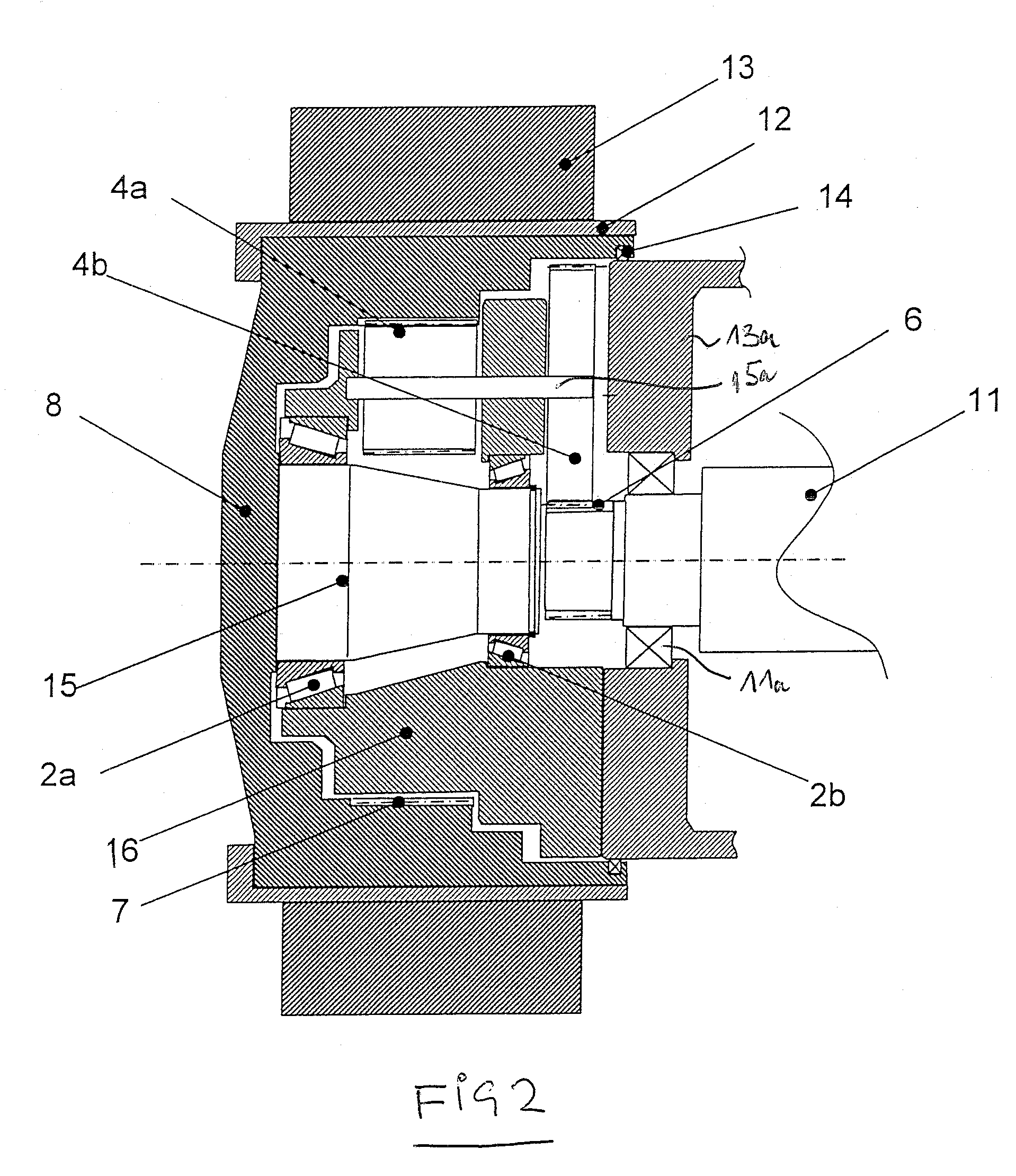
[0030]At the end of the driving shaft 11, a spicket 6 is formed on, which can be also separately disposed splinedly on the shaft 11, however. It meshes with planet wheels 4b, which are held and mounted in beatings in a planet carrier 1. The plane...


PUM


Abstract

A wheel hub drive with drive motor and drive gear system for industrial trucks, with the following features: driving and output axis of the drive gear system, rotation axis of the wheel and driving axis of the drive motor are disposed coaxially; the drive gear system is a single step or multi step planetary stepping gear system or a two or more step planetary coupler mechanism gear system, two horizontally spaced wheel bearings are located inside the drive gear system, wherein, a first wheel bearing is disposed between a first bearing portion, connected with the wheel hub, and a frame-fixed planet carrier, and a second wheel bearing is disposed between the first bearing portion and a frame-fixed second bearing portion or the frame-fixed planet carrier.

Description

CROSS-REFERENCE TO RELATED APPLICATIONS[0001]Not applicable.STATEMENT REGARDING FEDERALLY SPONSORED RESEARCH[0002]Not applicable.BACKGROUND OF THE INVENTION[0003]Wheel hub drives are frequently used for the travelling drive of industrial trucks. These are a combination of a wheel bearing and a gear system for the transformation of the driving torques and rotation numbers. Wheel hub drives are used in industrial trucks for unsteered as well as for steered wheels. The gear system transmits the driving torque from the drive motor to the driving wheel. The wheel bearing serves to support the vertical forces of the wheels. The space for construction is normally extremely limited, so that a compact construction is required.[0004]In the state of the art, a series of wheel hub drives has become known. From EP 1 167 140 B1, the entire contents of which is incorporated herein by reference, or DE 102 58 913 A1, the entire contents of which is incorporated herein by reference, wheel hub drives ...

Claims


Application Information

Patent Timeline
IPC IPC(8): B60K1/00
CPCB60K7/0007B60K7/0015B60K17/046B60K2007/0046B60K2007/0092F16D2121/20B60Y2200/15B62D5/0418B62D7/023B62D15/021B66F9/07572B60T1/10
Inventor ROGG, ANDREAS
Owner JUNGHEINRICH AG
Why Eureka
Try Eureka