
Process and System for Removing Contaminants from a Natural Gas Stream

Inactive Publication Date: 2007-11-22
SHELL OIL CO
View PDF4 Cites 21 Cited by
  • Summary
  • Abstract
  • Description
  • Claims
  • Application Information

AI Technical Summary

Benefits of technology

[0015] The process of the invention allows an advantageous and efficient treatment of the part of the natural gas stream (first gas stream) that is used for regeneration.
[0016] Regenerating the first adsorbent bed results in an increase in contaminants content of the second gas stream leaving the bed as compared to the first gas stream entering the bed. Although in this way the adsorbent bed can be regenerated, the regeneration gas now is of (far) worse quality than the original natural gas stream. This is a problem since it is generally desired to recycle the regeneration gas stream to an adsorbent bed in adsorption mode. In the prior art, this problem is solved by cooling the regeneration gas in an air and water cooler, so as to condense part of the contaminants into a liquid phase, and by separating the liquid phase from the regeneration gas.
[0019] In this way actually a better quality of the regeneration gas can be obtained than the original natural gas stream. So the regeneration gas is first enriched in contaminants, and then contaminants are removed so that overall the contaminants level is decreased.
[0021] When the lean gas stream is then contacted with the second adsorbent bed, together with the other part of the natural gas stream, a purified gas stream can be obtained that is of better quality than what is obtainable with the known process, due to the better quality of the lean gas that is recycled from regeneration. It has been found that this is a very efficient way to improve the quality of the purified gas, just sufficiently to obtain required specifications in many practical situations, without having to modify other parts of the process such as the absorption step. The present invention moreover helps to minimize the fraction of the natural gas stream that has to be used for regeneration.

Problems solved by technology

Although in this way the adsorbent bed can be regenerated, the regeneration gas now is of (far) worse quality than the original natural gas stream.
This is a problem since it is generally desired to recycle the regeneration gas stream to an adsorbent bed in adsorption mode.

Method used


Image

  • Process and System for Removing Contaminants from a Natural Gas Stream
  • Process and System for Removing Contaminants from a Natural Gas Stream

Examples


example 1

Comparative Example

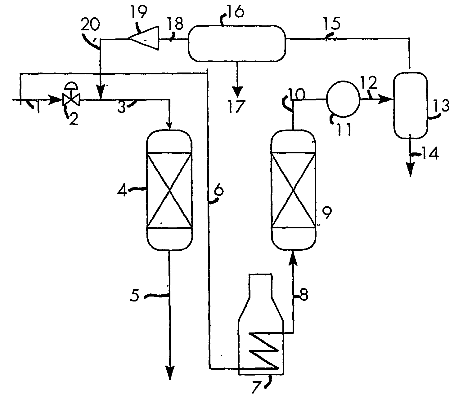
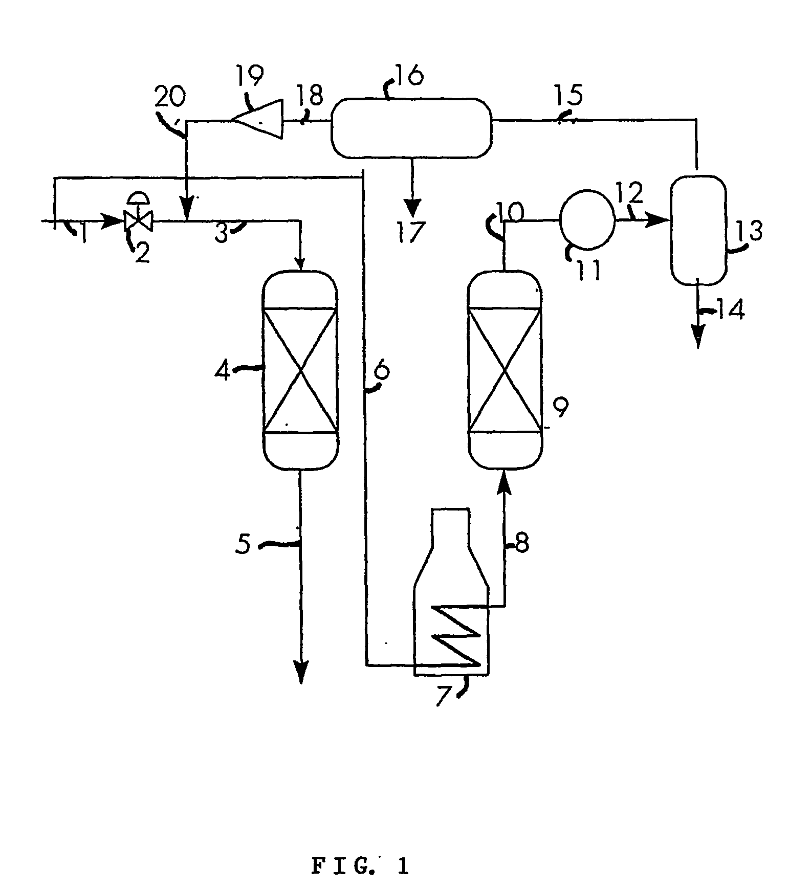
[0087] In the comparative example use is made of a line-up as shown in FIG. 1, but without the separator means 16 and compressor 19. Part of a feed natural gas stream having a composition as shown in Table 1 is contacted with a second adsorbent bed, the second adsorbent bed being in the adsorbing mode. The pressure of the feed gas stream is 80 bara. The temperature of the feed gas is 25° C. Another part (for example 30%) of the feed gas stream is heated to obtain a first heated gas stream. The heated first gas stream is contacted with a first adsorbent bed, the first adsorbent bed being in the regeneration mode, to create a second gas stream enriched in water and C5+ hydrocarbons. The second gas stream is cooled to a temperature such that water and hydrocarbons condense into a first liquid water / hydrocarbon phase. The first liquid water / hydrocarbon phase is separated. The composition of the resulting gas stream is given in Table 1. The resulting gas stream that i...

example 2

[0088] A feed gas having a composition as shown in Table 2 is subjected to a process based on example 1, but now according to the present invention as described in FIG. 1, the cooling device (16) being an accelerated inertia separator. The resulting composition of the 2nd, 3rd and 4th (lean) gas stream are given in Table 2.

TABLE 2Composition of gas streams in example 2 (in mol %).2nd gas3rd gas4th gasFeedstreamstreamstreamC194.713893.564094.388695.0137C21.25361.23071.22821.2220C30.11440.11060.10770.1035N20.49810.49260.49820.5023CO22.81842.77752.79022.7966He0.00010.00010.00010.0001iC40.02090.01970.01850.0167NC40.03080.02850.02620.0224NC50.19920.24770.20030.1255NC60.14940.76590.48110.1609NC70.10000.43960.18140.0244BNZN0.00000.00040.00030.0001NC80.02000.06070.01400.0007TOLU0.00000.00000.00000.0000NC90.01500.03900.00450.0001NC100.00800.01940.00100.0000H2O0.05830.20360.05980.0110100.0000100.0000100.0000100.0000

[0089] It can be seen in this example that overall contaminants have been re...

example 3

[0090] A feed gas having a composition as shown in Table 3 is subjected to a process as described in FIG. 1, the cooling device (16) being a refrigerator, run at 80 bar and −7° C. The resulting composition of the 2nd, 3rd and 4th (lean) gas stream are given in Table 3.

TABLE 3Composition of gas streams in example 3 (in mol %).2nd gas3rd gas4th gasFeedstreamstreamstreamC194.713893.537394.408594.8961C21.25361.23001.22721.2181C30.11440.11070.10760.1038N20.49810.49260.49850.5023CO22.81842.77592.78922.7886He0.00010.00010.00010.0001IC40.02090.01980.01850.0171NC40.03080.02880.02630.0235NC50.19920.23420.18680.1393NC60.14940.76110.46550.2433NC70.10000.48730.19290.0572BNZN0.00000.00050.00030.0001NC80.02000.06230.01360.0019TOLU0.00000.00000.00000.0000NC90.01500.03900.00420.0003NC100.00800.01940.00100.0000H2O0.05830.20100.05980.0082100.0000100.0000100.0000100.0000

[0091] Also in this example that the total methane content is higher as compared to the comparative example, be it somewhat lower th...


PUM

PropertyMeasurementUnit
Temperatureaaaaaaaaaa

Abstract

A process and system for removing contaminants from a natural gas stream, the process comprising the steps of: (a) contacting part of the natural gas stream as a first gas stream at an elevated temperature with a first adsorbent bed in regeneration mode, to remove contaminants present on the first adsorbent bed, and to obtain a second gas stream that is enriched in contaminants compared to the first gas stream; (b) submitting the second gas stream to a gas / liquid separation step comprising cooling the second gas stream to a temperature such that at least some contaminants begin to condense into a first liquid phase that is rich in contaminants, and separating the first liquid phase from the second gas stream to create a third gas stream; wherein the gas / liquid separation step forms a first gas / liquid separation step, and wherein the process further comprises (c) submitting the third gas stream to a second gas / liquid separation step to obtain a second liquid phase that is rich in contaminants, and a lean gas stream.

Description

FIELD OF THE INVENTION [0001] The invention relates to a process for removing water and hydrocarbons from a natural gas stream. BACKGROUND OF THE INVENTION [0002] The term “natural gas” is applied to gas produced from underground accumulations of widely varying composition. The main constituent of natural gas is methane. Apart from methane, natural gas generally includes other hydrocarbons, nitrogen, carbon dioxide, sometimes a small proportion of hydrogen sulphide, and often water. Hydrocarbon constituents include ethane (C2), propane (C3), butane (C4), pentane (C5), hexane (C6), heptane (C7), etc. Hydrocarbons having 5 or more carbon atoms are generally referred to as C5+. Constituents of a natural gas stream other than methane will be referred to as contaminants in the specification and in the claims. The invention relates in particular to the removal of contaminants by partial condensation followed by gas / liquid separation, and contaminants that can be removed in this way are al...

Claims


Application Information

Patent Timeline
IPC IPC(8): C10G5/02B01D5/00C10L3/10
CPCB01D5/0054C10L3/102C10L3/10C10G5/02
Inventor NEUMANN, KLAUS DIETER KARLRAJANI, JAYANTILAL BHAGVANJI
Owner SHELL OIL CO
Learn More