

Method for forming a temporary hermetic seal for an OLED display device
- Summary
- Abstract
- Description
- Claims
- Application Information
AI Technical Summary
Benefits of technology
Problems solved by technology
Method used
Image

Examples
example 1
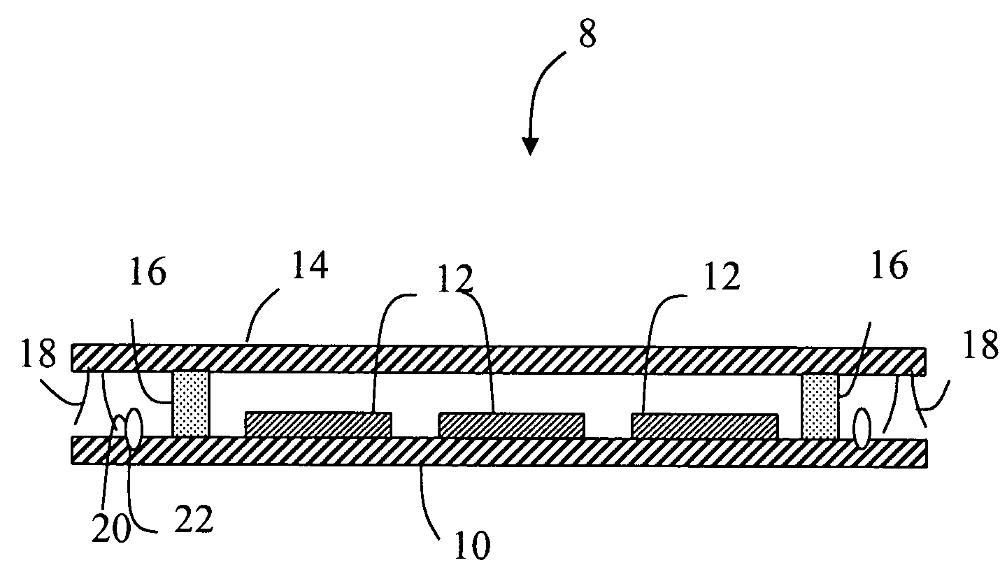
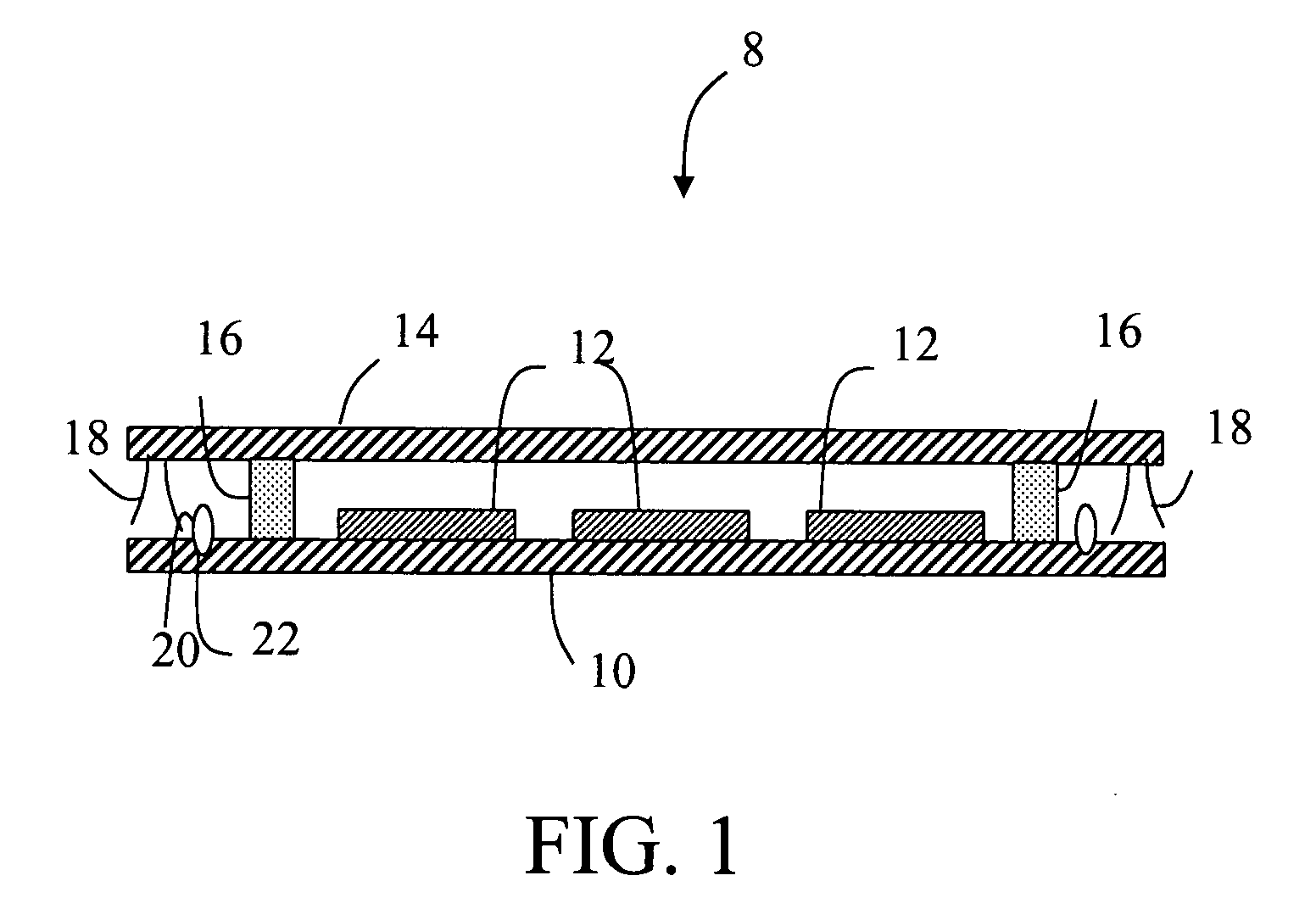
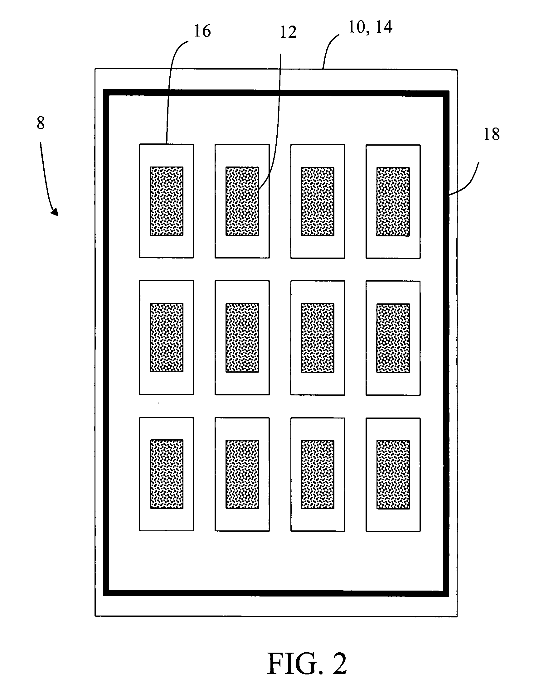
[0027]A first and second glass cover substrate was provided. Each substrate was about 0.7 mm in thickness and 6 inch (15.24 cm) square. Each of the glass cover substrates included frit frames disposed thereon in an m×n pattern.
[0028]First and second back plane substrates were also provided having dimensions the same as the cover substrates. To represent individual OLED display devices and to provide a visual confirmation of hermeticity, calcium metal films were deposited in an m×n matrix on the surface of each back plane substrate. If exposed to air, the calcium metal film transforms from having a silvery surface to being milky in appearance. The thickness of the calcium films on the first substrate were approximately 600 nm, while the thickness of the calcium films on the second substrate were approximately 700 nm.
[0029]A vacuum grease (Dow-Corning High Vacuum Grease (15 V 2645 Stopcock / Vacuum Grease, 150 g. Tube) was dispensed with a syringe around the perimeter of each cover subs...
example 2
[0032]A second experiment was conducted similar to that described in Example 1 above. Six assemblies were constructed. Two assemblies were constructed using Santovac 5 GB Ultra High Vacuum Grease as a sealant, two assemblies were constructed using Braycote 600EF High Vacuum Grease as a sealant, and two assemblies were constructed using Apiezon M High Vacuum Grease as a sealant. The sealant in all cases was dispensed using an air-powered syringe application tips and adapters from the EFD® company. One calcium film (emulating an OLED device) on a single Bracote assembly failed after 337 hours, a second “device” failed after 33381 hours, and a third device failed after 522 hours. All other samples exceeded 882 hours of hermeticity.
PUM
 Abstract
Description
Claims
Application Information