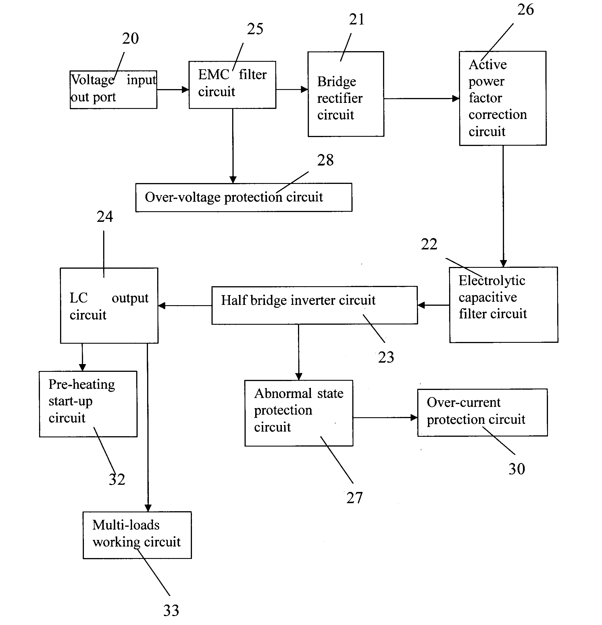
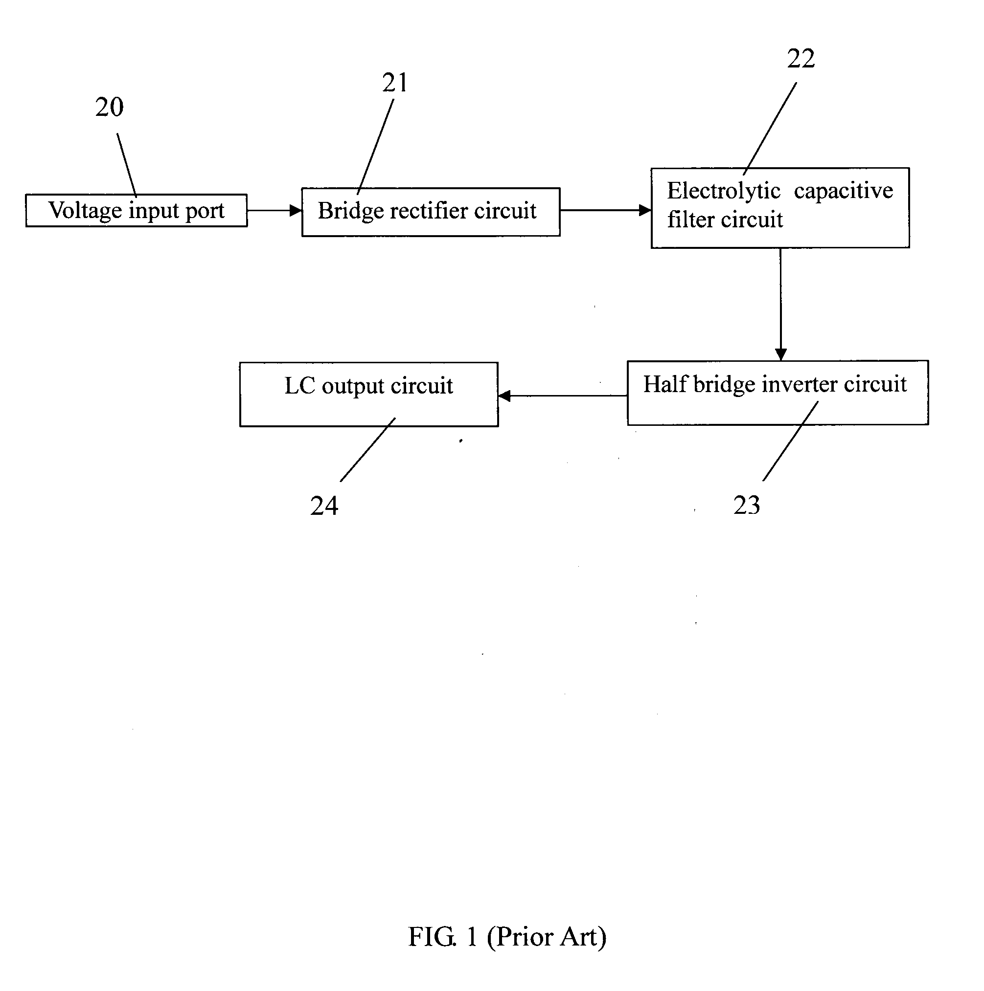
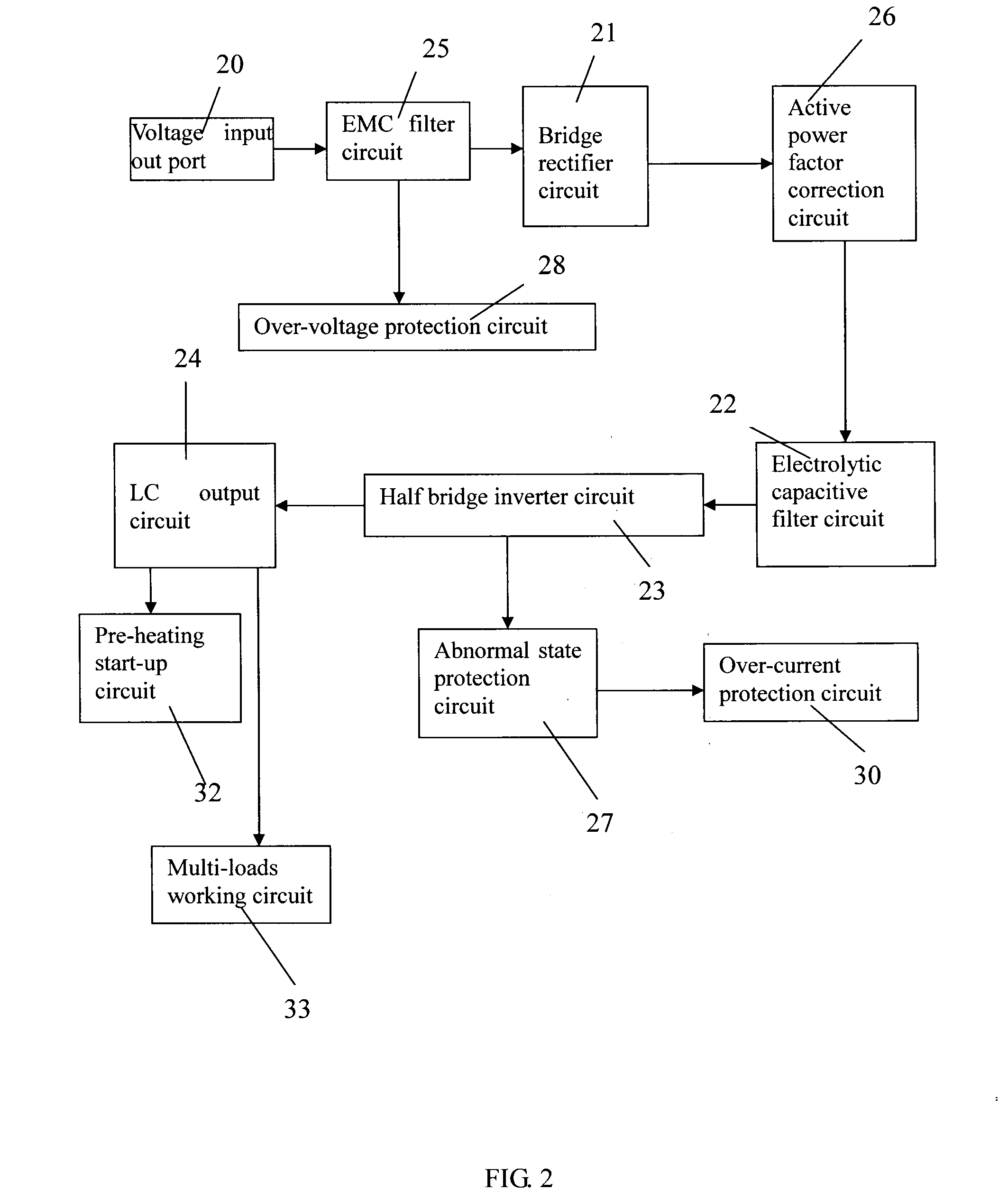
Power-Saving and Stabilizing Ballast
a ballast and stabilizer technology, applied in the field of power saving and stabilizing ballast, can solve the problems of high temperature, high shock noise of ballast, flickering of lamps or lanterns with such ballast, etc., and achieve the effects of suppressing surge currents effectively, enhancing coil power factor, and reducing nois
- Summary
- Abstract
- Description
- Claims
- Application Information
AI Technical Summary
Benefits of technology
Problems solved by technology
Method used
Image

Examples
first embodiment
[0041]FIG. 8 is a circuit diagram of the pre-heating start-up circuit 32 of the present invention. An LC resonant circuit composed of a first capacitor 321 and an inductance 322 has a fluorescent lamp 320 connected therein in series. A second capacitor 323 and a thermosensitive element such as a positive temperature coefficient (PTC) resistor 324 connect respectively in parallel to the fluorescent lamp 320. When the pre-heating start-up circuit starting, the resistance of the PTC resistor 324 is low, thereby to limit the voltage of the fluorescent lamp 320, which prevents the cathode of the lamp from glow discharge. The temperature and the resistance of the PTC resistor 324 increase with time. After 0.4 s to 1.5 s, the voltage of the second capacitor 323 increases rapidly to breakdown and enkindle the cathode of the lamp 320.
[0042]FIG. 9 is a circuit diagram of a second embodiment of the pre-heating start-up circuit 32 of the present invention which is similar with that shown in the...
second embodiment
[0045]FIG. 12 shows a multi-loads working circuit 33′ of the present invention. The multi-loads working circuit 33′ is a current push-pull lamps output circuit for making four fluorescent lamps work simultaneity. Because the current push-pull lamps output circuit of the present invention is well known to persons ordinarily skilled in the art, a detailed description of such structure is omitted here from.
PUM
 Abstract
Description
Claims
Application Information
 - R&D
- Intellectual Property
- Life Sciences
- Materials
- Tech Scout
- Unparalleled Data Quality
- Higher Quality Content
- 60% Fewer Hallucinations
Browse by: Latest US Patents, China's latest patents, Technical Efficacy Thesaurus, Application Domain, Technology Topic, Popular Technical Reports.
© 2025 PatSnap. All rights reserved.Legal|Privacy policy|Modern Slavery Act Transparency Statement|Sitemap|About US| Contact US: help@patsnap.com