

Display Device
- Summary
- Abstract
- Description
- Claims
- Application Information
AI Technical Summary
Benefits of technology
Problems solved by technology
Method used
Image

Examples
first embodiment
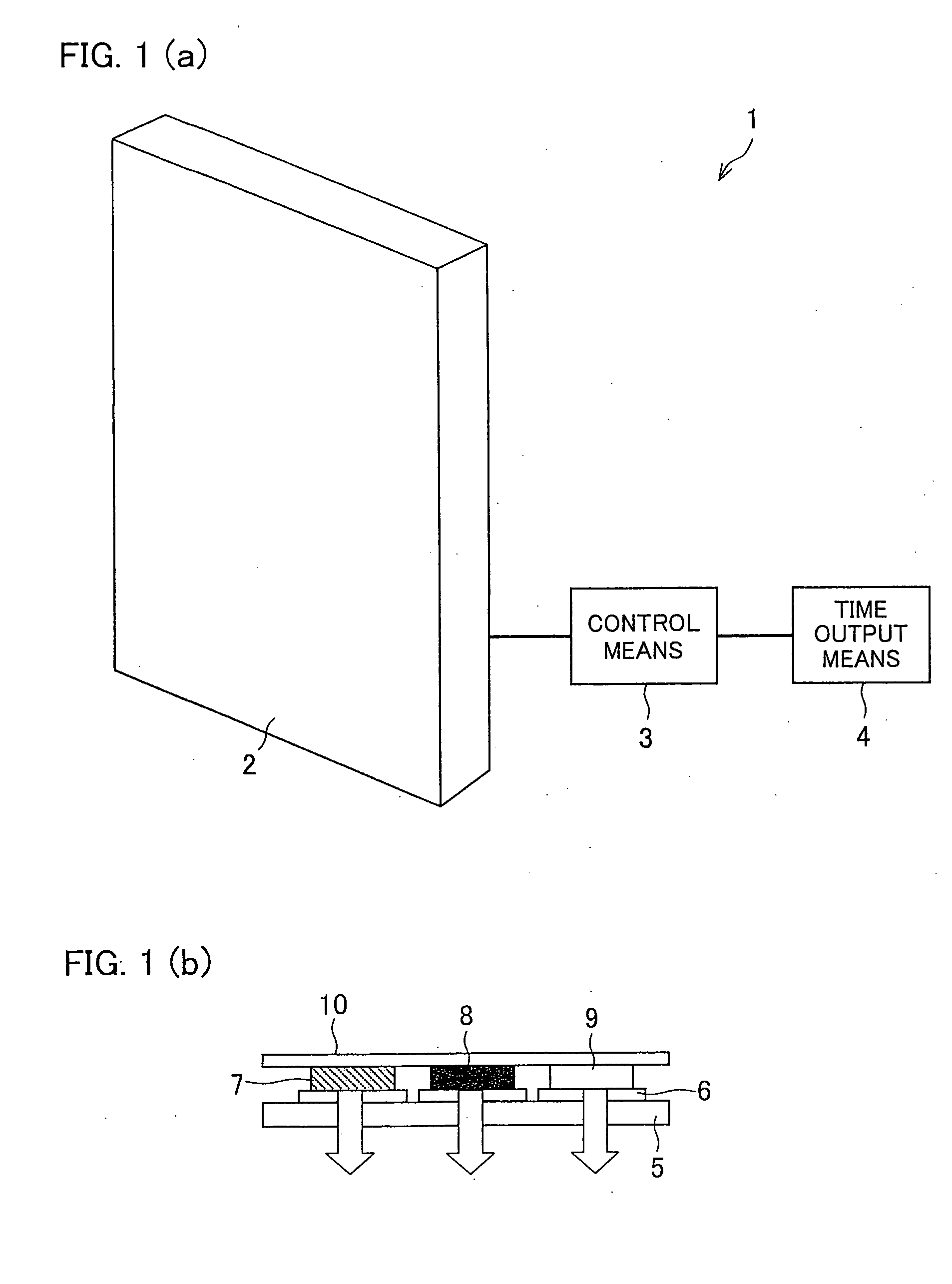
[0041] A display device according to one embodiment of the present invention will be described below with reference to FIG. 1. As illustrated in FIG. 1(a), a display device 1 of the present embodiment includes an organic EL (electroluminescent) panel 2 (image display section) for displaying information such as an image, control means 3 for controlling a current to be applied to each pixel of the organic EL panel 2, and time output means 4 for outputting to the control means 3 time information indicating the current time.
[0042] The organic EL panel 2 includes a large number of cells. As illustrated in FIG. 1(b), each of the cells includes a glass substrate 5, an anode 6, an organic layer (second light emitter) 7 for emitting red light, an organic layer (third light emitter) 8 for emitting green light, an organic layer (first light emitter) 9 for emitting light having a dominant wavelength of approximately 464 nm, and a cathode 10.
[0043] The meaning of the term “dominant wavelength”...
second embodiment
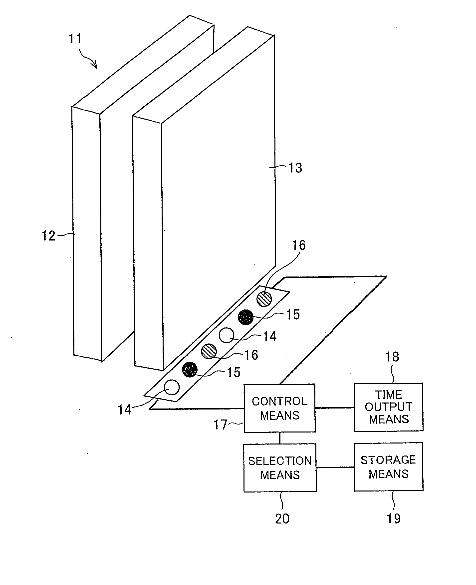
[0069] A display device according to another embodiment of the present invention will be described below with reference to FIGS. 5 to 9. As illustrated in FIG. 5, a liquid crystal display device (display device) 11 of the present embodiment includes a liquid crystal panel (image display section) 12 for displaying information such as an image, an optical waveguide plate 13, LEDs (first light emitters) 14 each of which emits light having a dominant wavelength of approximately 464 nm, LEDs (second light emitters) 15 each of which emits red (R) light, and LEDs (third light emitters) 16 each of which emits green (G) light.
[0070] Each of the LEDs 14, 15, and 16 serves as a light emitter for the optical waveguide plate 13. The optical waveguide plate 13 transmits, to the liquid crystal panel 12, light emitted by the LEDs 14, 15, and 16.
[0071] Note that components having the same functions as those described in the foregoing embodiment are given the same reference numerals. In FIG. 5, for...
third embodiment
[0100] A display device according to a further embodiment of the present invention will be described below with reference to FIGS. 10 and 11. A liquid crystal display device (display device) 21 of the present embodiment includes a liquid crystal panel 12 for displaying information such as an image, an optical waveguide plate 13 for irradiating a back surface of the liquid crystal panel 12, a cold cathode fluorescent lamp (white light emitter) 22, LEDs 14 each of which has a dominant wavelength of approximately 464 nm, control means 17 for controlling a luminous intensity of the LED 14, and time output means 18 for outputting current time information, each of the cold cathode fluorescent lamp 22 and the LEDs 14 serving as a light emitter for the optical waveguide plate 13.
[0101] A process will be described below by which the luminous intensity is controlled in the liquid crystal display device 21 of the foregoing arrangement. During use of the display device, the cold cathode fluore...
PUM
 Abstract
Description
Claims
Application Information