
Methods and systems for LCD backlight color control

Inactive Publication Date: 2007-11-22
O2 MICRO INC
View PDF2 Cites 34 Cited by
  • Summary
  • Abstract
  • Description
  • Claims
  • Application Information

AI Technical Summary

Benefits of technology

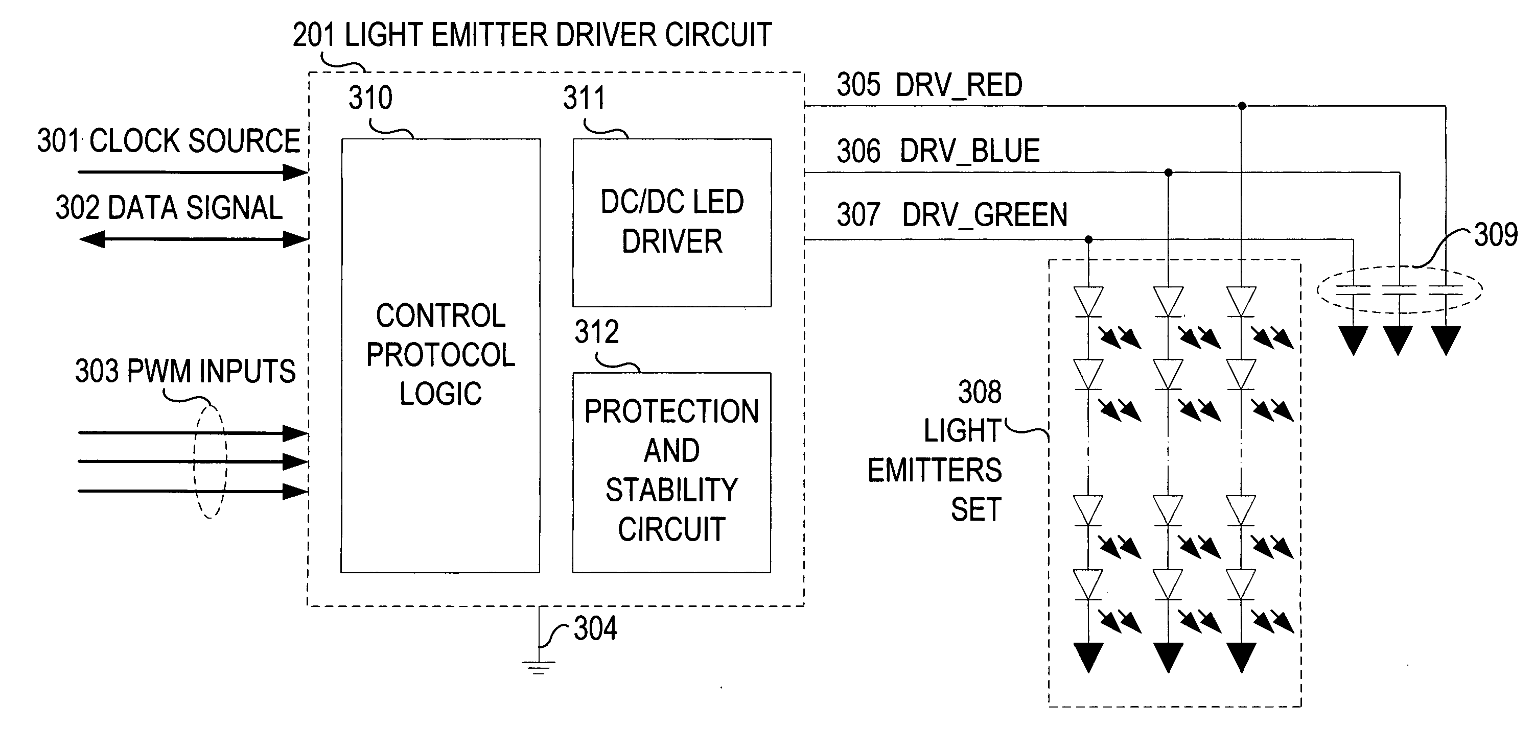
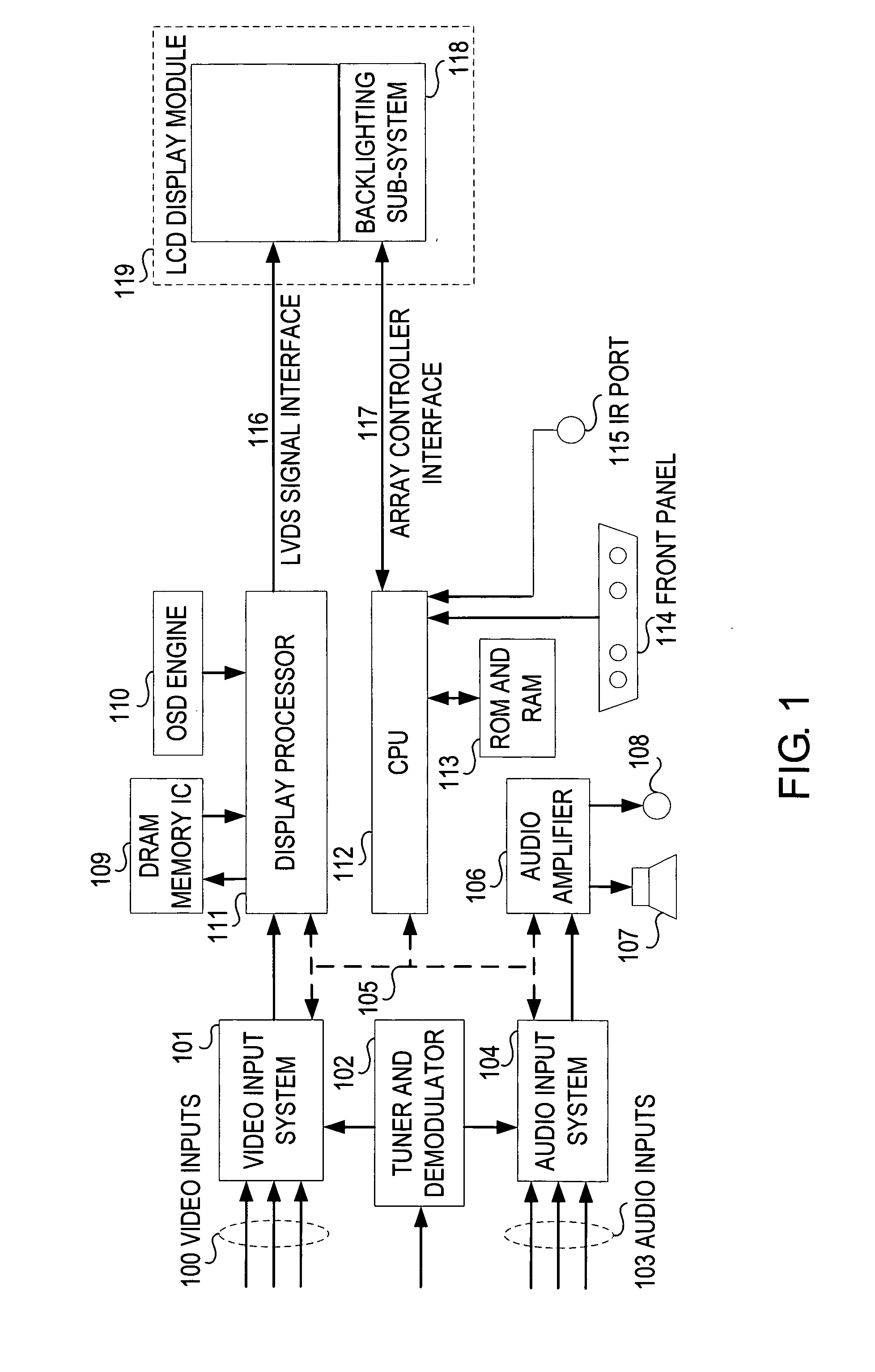
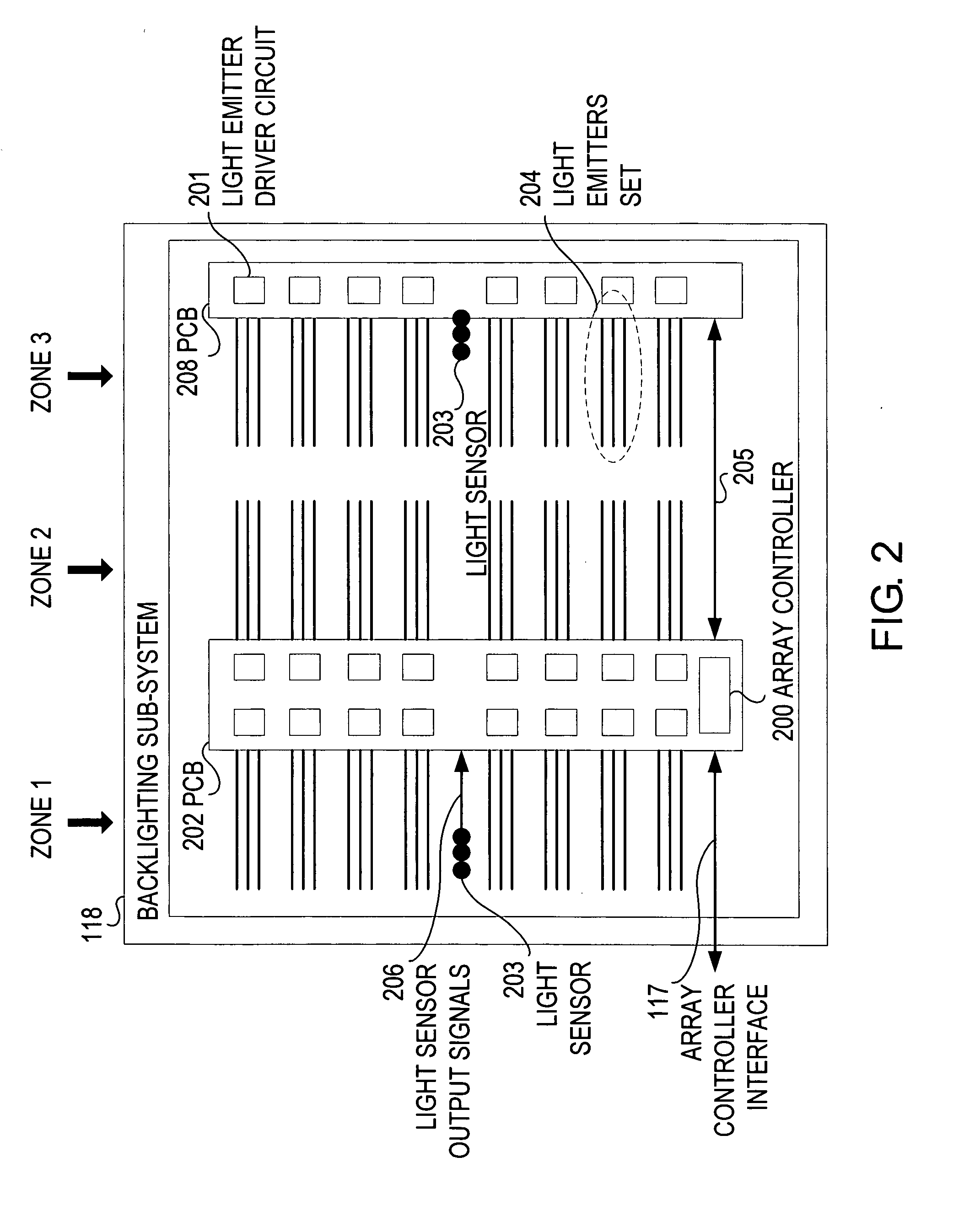
[0018]Accordingly, various embodiments of the present invention disclose a low-cost, highly flexible approach to managing the LCD backlight color of RGB systems. The present invention provides for advantages such as easy modification of color management algorithms operating on a display system. The algorithms can be quickly modified to meet design criteria and constraints, such as emitter matrix configuration, and easily tuned and calibrated to specific system requirements. The ease of modifying algorithms offers LCD display system manufacturers a way to differentiate their products based on unique backlight color management algorithms. Another advantage is the array controller offering a central point of communication between the CPU and light emitter driver circuits can offer cost advantages. For example, the light emitter driver circuits do not need to be individually addressed by an input / output communications protocol directly, removing the need for such protocol logics and address configuration terminals. Two or three address configuration terminals are used for devices based on Philips I2C protocol to select the slave address. Similarly, the protocol logics and interface terminals may be reduced by a central communications point to a set of color sensors.

Problems solved by technology

Additionally, the RGB system is challenged by hue and saturation associated with a given color name that can vary over a considerable range, a range that is further complicated by several variations of different kinds of display monitor technologies, and a range of characteristics among manufacturers and models of monitors within a technology.

Method used


Image

  • Methods and systems for LCD backlight color control
  • Methods and systems for LCD backlight color control
  • Methods and systems for LCD backlight color control

Examples


Embodiment Construction

[0017]Reference will now be made in detail to the preferred embodiments of the present invention, methods and systems for LCD backlight color control, examples of which are illustrated in the accompanying drawings. While the invention will be described in conjunction with the preferred embodiments, it will be understood that they are not intended to limit the invention to these embodiments. On the contrary, the invention is intended to cover alternatives, modifications and equivalents, which may be included within the spirit and scope of the invention as defined by the appended claims.

[0018]Accordingly, various embodiments of the present invention disclose a low-cost, highly flexible approach to managing the LCD backlight color of RGB systems. The present invention provides for advantages such as easy modification of color management algorithms operating on a display system. The algorithms can be quickly modified to meet design criteria and constraints, such as emitter matrix config...


PUM


Abstract

The present invention provides a low-cost, highly flexible display system which comprises a programmable CPU, a LCD module for displaying visual information, an array of light emitters for providing backlighting to the LCD module, an array of light emitter driver circuits, and an array controller. The programmable CPU accesses ROM and RAM memory and comprises at least one input / output protocol for communicating with components on the display system. A single light driver circuit controls the intensity of a set of light emitters. The array controller connects to a number of light emitter driver circuits and acts as a central point of communication between the CPU and the array of light emitter driver circuits and color sensors.

Description

FIELD OF THE INVENTION[0001]The present invention relates to the design and manufacturing of display systems, the devices on display systems, and the methods for managing Liquid Crystal Display (LCD) backlighting for display systems.BACKGROUND ART[0002]One example color space is the International Commission on Illumination (CIE) system, that characterizes colors by a luminance parameter and two color coordinates which specify a point on the CIE chromaticity diagram. The CIE system is factored by sensitivity curves which have been measured for the human eye, and covers the scope of color perception called the gamut of human color vision.[0003]Conventional approaches to providing a color gamut on computer monitor and entertainment display systems match colors in the CIE system by combining a given set of three primary colors (such as red, green, and blue), and provide a range of color represented on the CIE system by a triangular region joining the coordinates of the three colors. Thi...

Claims


Application Information

Patent Timeline
IPC IPC(8): G09G3/36
CPCG09G3/3413G09G2360/145G09G2330/045G09G2320/0242
Inventor MORROW, NEIL
Owner O2 MICRO INC
Learn More