Display Device

Inactive Publication Date: 2007-11-22
PANASONIC LIQUID CRYSTAL DISPLAY CO LTD +1
View PDF5 Cites 85 Cited by
  • Summary
  • Abstract
  • Description
  • Claims
  • Application Information

AI Technical Summary

Benefits of technology

[0010] It is an object of the present invention to provide a display device having incorporated an ambient light sensor in a display panel which device is designed to reduce a manufacturing variation of each display panel, for improving output accuracy of the ambient light sensor.
[0011] In order to correct a variation of an output characteristic appearing in each ambient light sensor (ambient light sensing means), the ambient light sensor is installed adjacent to a backlight light sensor (backlight sensing means) for sensing a ray of backlight. This adjacent installation of these two light sensors makes the manufacturing variation even in each display panel. The operation is

Problems solved by technology

Hence, the capability of modulating light is required to be corrected in each li

Method used


Image

  • Display Device
  • Display Device
  • Display Device

Examples


first embodiment

[0030] The first embodiment of the present invention will be described with reference to FIGS. 1 to 6.

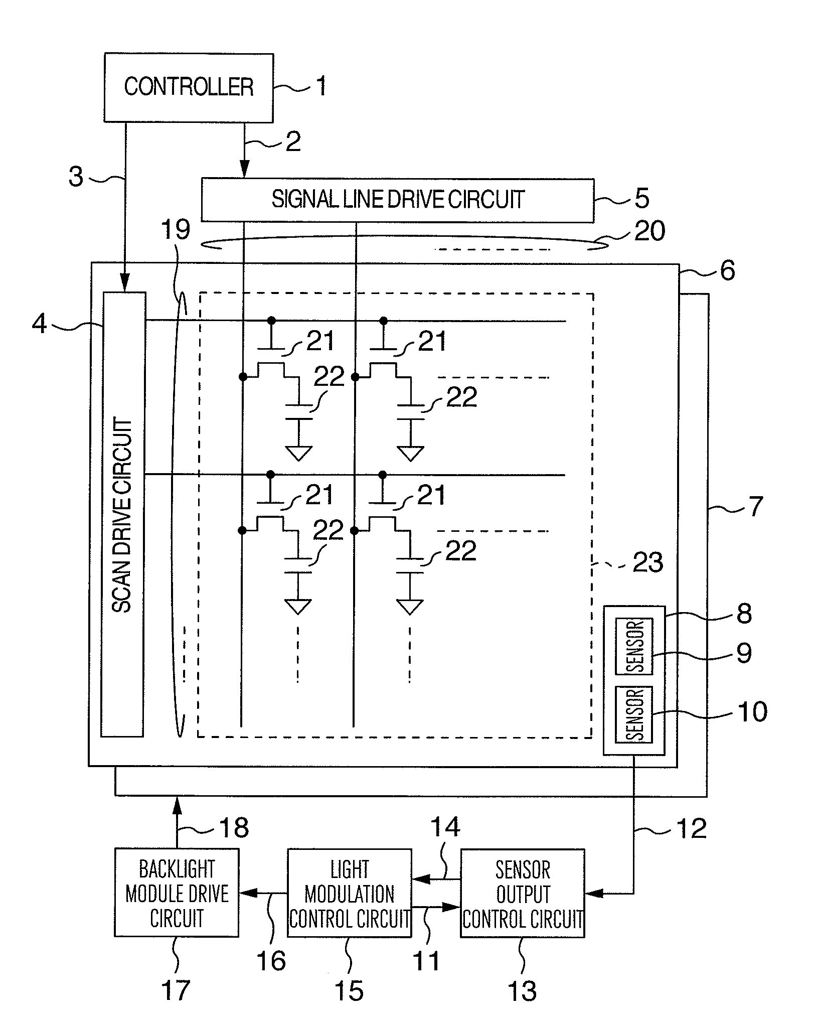
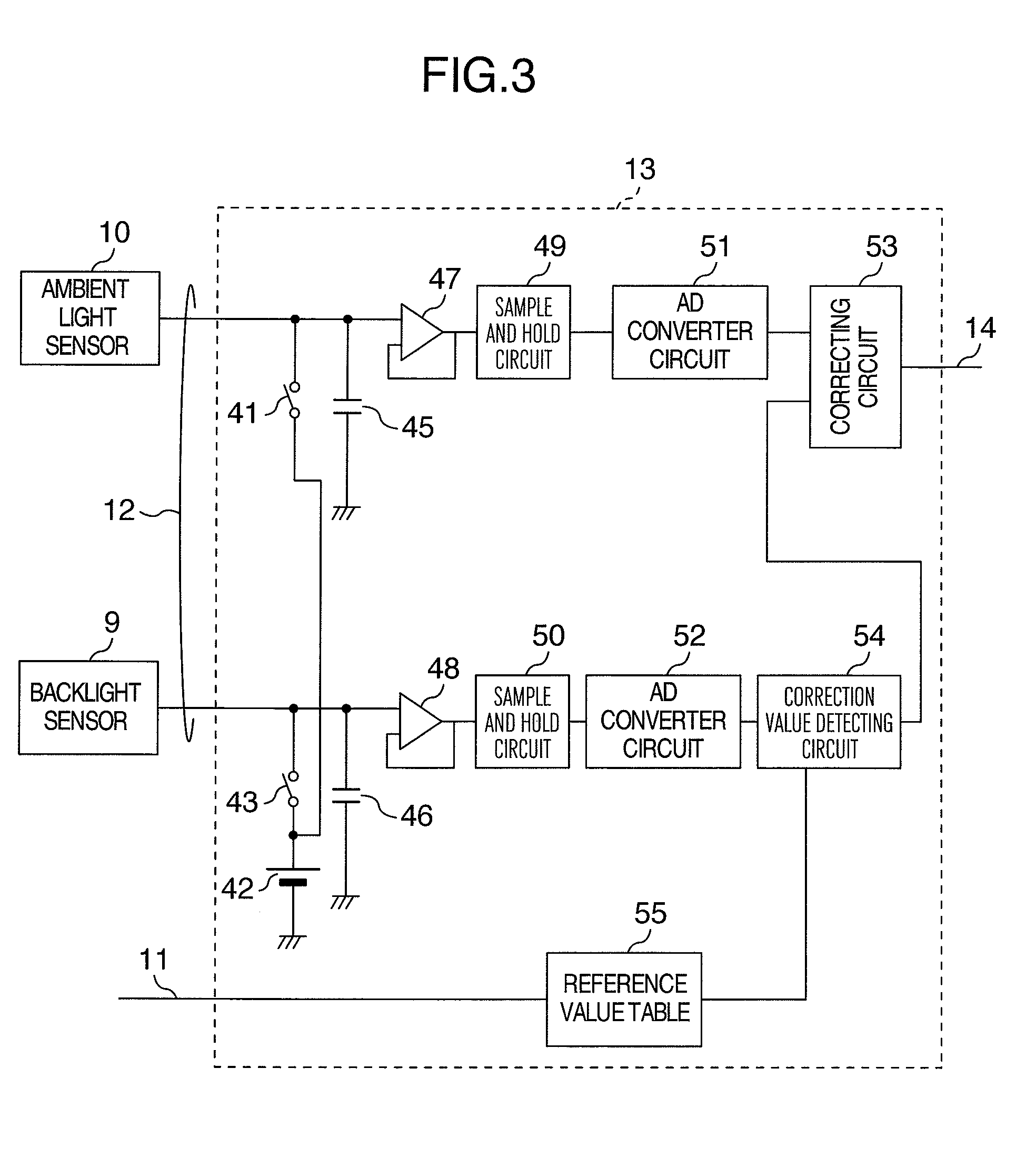
[0031]FIG. 1 is a block diagram showing a liquid crystal display device according to the present invention. A numeral 1 denotes a controller, a numeral 2 denotes display data, a numeral 3 denotes a control signal, a numeral 4 denotes a scan line drive circuit, a numeral 5 denotes a signal line drive circuit, a numeral 6 denotes a liquid crystal panel, a numeral 7 denotes a backlight module, a numeral 8 denotes a light sensor pair formed in the liquid crystal panel 6, a numeral 9 denotes a backlight sensing means (backlight sensor) of the light sensor pair 8, a numeral 10 denotes an ambient light sensing means (ambient light sensor) of the light sensor pair 8, a numeral 11 denotes light modulation setting data (to be used for setting a light modulation level), a numeral 12 denotes a light sensor output, a numeral13 denotes a sensor output control circuit, a numeral 14 denotes a corr...

second embodiment

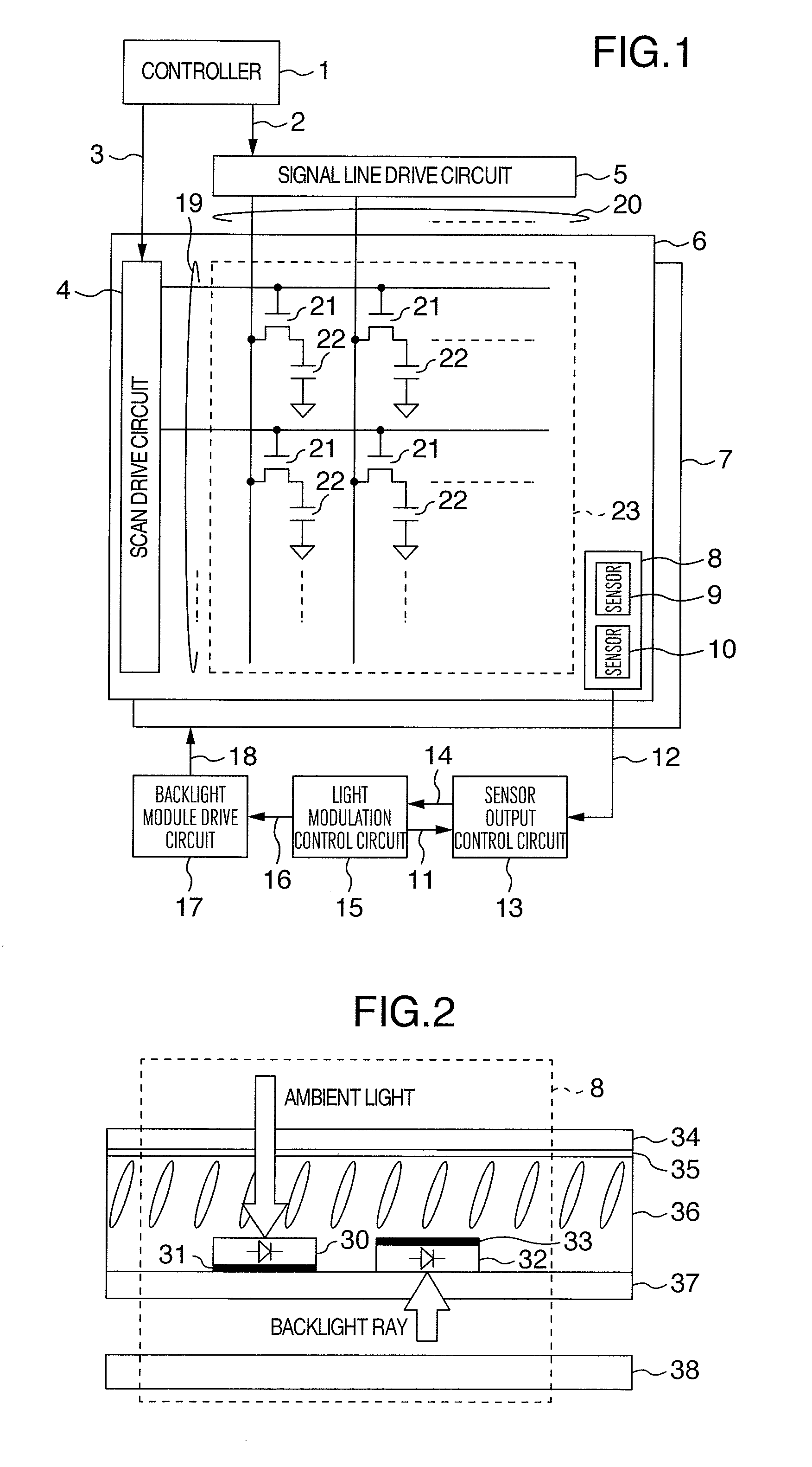
[0059] The second embodiment of the present invention will be described with reference to FIG. 7. The display operation of the liquid crystal display device and the light modulation control to be executed through the light sensors are the same as those described with respect to the first embodiment. The sectional structure of the light sensor pair 8 of the second embodiment is different from that shown in FIG. 2.

[0060]FIG. 7 shows a partial sectional structure of the light sensor pair 8. The difference of the structure shown in FIG. 7 from that of the first embodiment shown in FIG. 1 is a backlight shading film 31a and an ambient light shading film 33a. The film 31a is located outside of the lower glass substrate 37 and the film 33a is located outside of the upper glass substrate 34. The location of these light shading films outside of the glass substrates makes it possible to reduce the manufacturing cost of the liquid crystal panel.

third embodiment

[0061] The third embodiment of the present invention will be described with reference to FIG. 8. The display operation of the liquid crystal display device and the light modulation to be executed through the light sensors are the same as those described with respect to the first embodiment. The difference between the third embodiment and the first embodiment is location of the light sensor pair 8 shown in FIG. 2.

[0062]FIG. 8 shows a partial sectional structure of the light sensor pair 8 including an ambient light sensor 70, a backlight shading film 71, a backlight sensor 72, an ambient light shading film 73, an upper glass substrate 77, a color filter 75, a liquid crystal layer 76, a lower glass substrate 74, and a backlight unit 78. The difference of this structure shown in FIG. 8 from that of the first embodiment shown in FIG. 2 is a TFT element formed on the side of the upper glass substrate 77.

[0063] Since the ambient light sensor 70 is located on the upper glass substrate 77,...


PUM


Abstract

An ambient light sensor 10 and a backlight sensor 9 are located on the liquid crystal panel 6 adjacently to each other, for correcting a variation of an output characteristic of the ambient light sensor 10. This location keeps the manufacturing variation of each liquid crystal panel 6 even in these two light sensors 9 and 10. A degree of variation of an output of the backlight sensor 9 for sensing a ray of backlight from a backlight module relative to a predetermined reference value is detected. Based on the detected result, the output of the ambient light sensor 10 is corrected. This operation makes it possible to improve sensing accuracy of the ambient light sensor 10 and keep the light modulation even in each liquid crystal panel provided with the ambient light sensor 10.

Description

INCORPORATION BY REFERENCE [0001] The present application claims priority from Japanese application JP2006-136377 filed on May 16, 2006, the content of which is hereby incorporated by reference into this application. BACKGROUND OF THE INVENTION [0002] The present invention relates to a display device which provides a capability of modulating a luminance of a backlight ray to be radiated to a rear surface of a display panel according to the ambient illuminance. [0003] A liquid crystal display device, in particular, a liquid crystal display device used in a portable instrument, is equipped with a capability of modulating a luminance of a backlight ray according to the ambient illuminance for the purpose of improving visibility and image quality of the display screen whenever the display device may be located indoors or outdoors. [0004] For example, when the display device is located in an environment with high ambient light such as an outdoor place in clear weather and daytime, the lu...

Claims


Application Information

Patent Timeline
IPC IPC(8): G09G3/36
CPCG09G3/3406G09G2360/145G09G2360/144G09G2320/0633
Inventor NITTA, HIROYUKISATO, HIDEOKUDO, YASUYUKI
Owner PANASONIC LIQUID CRYSTAL DISPLAY CO LTD
Why Eureka
Try Eureka