
Magnetic detection apparatus

a detection apparatus and magnetic technology, applied in the direction of magnetic measurement, measurement devices, instruments, etc., can solve the problems of limited accuracy of detecting the position of projections and depressions of magnetic moving bodies, b>1/b>, etc., and achieve the effect of reducing the variation of the detection accuracy of rotary moving bodies

Active Publication Date: 2016-10-27
MITSUBISHI ELECTRIC CORP
View PDF2 Cites 2 Cited by
  • Summary
  • Abstract
  • Description
  • Claims
  • Application Information

AI Technical Summary

Benefits of technology

The invention is about a magnetic detection apparatus that can cancel out changes in resistance values caused by manufacturing variations. This is done by angling the pattern shapes of the magneto-resistance elements. This reduces the detection accuracy of a rotary moving body and improves accuracy.

Problems solved by technology

However, there is a need for improvement of detection accuracy in a magnetic detection apparatus as described above, but the accuracy for detecting the positions of projections and depressions of the magnetic moving body 1 is limited by variations on manufacturing in the relative positions of the magneto-resistance segments 2a and 2b and a magnet 3.

Method used


Image

  • Magnetic detection apparatus
  • Magnetic detection apparatus
  • Magnetic detection apparatus

Examples


embodiment 1

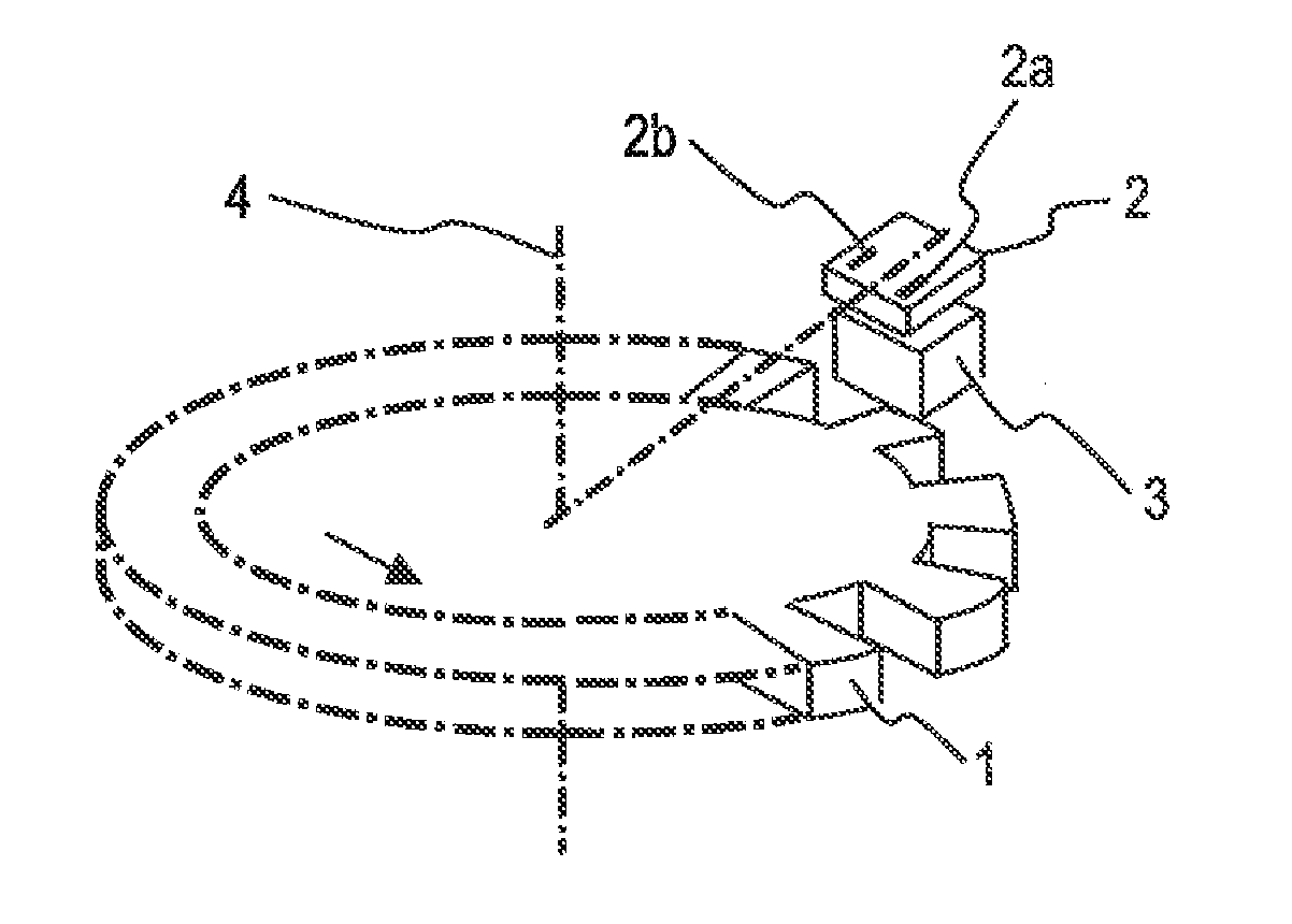
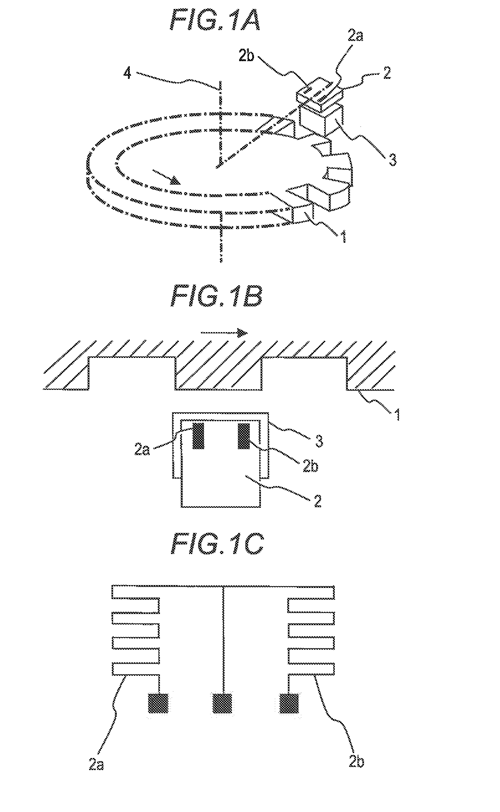
[0038]A magnetic detection apparatus according to embodiment 1 of the invention will be described with reference to the drawings FIG. 7A through 7D show the structure of the magnetic detection apparatus according to embodiment 1 of the invention. FIG. 7A is a perspective view, FIG. 7B is a plan view, and FIG. 7C is an enlarged view of a magneto-resistance segment.

[0039]In the drawing, reference numeral 1 indicates a magnetic moving body in which projecting shapes for changing a magnetic field are provided around, for example, a disc; 2 indicates a processing circuit unit having a board surface on which a circuit is printed; 2a and 2b indicate magneto-resistance segments; 3 indicates a magnet, and 4 indicates the rotary shaft of the magnetic moving body 1.

[0040]The magnetic moving body 1 rotates synchronously when the rotary shaft 4 rotates. Each of the magneto-resistance segments 2a and 2b is represented as a black block in FIG. 7B because the magneto-resistance segments 2a and 2b a...


PUM


Abstract

In a magnetic detection apparatus that prevents the output waveform from deviating regardless of whether two magneto-resistance elements are displaced relative to a magnet or accurately disposed relative to the magnet, the above two magneto-resistance elements are angled in consideration of a change in the direction of application of the magnetic field during displacement of the positional relationship and the anisotropy of the magneto-resistance elements so that the magneto-resistance elements are oriented in a direction in which the deviation of the output waveform caused by a change in the magnitude of application of the magnetic field during displacement of the positional relationship is cancelled, thereby preventing the detection accuracy of a magnetic moving body (detection target) being affected even if the magneto-resistance elements are displaced relative to the magnet due to manufacturing variations.

Description

BACKGROUND OF THE INVENTION[0001]1. Field of the Invention[0002]The present invention relates to a magnetic detection apparatus including a giant magneto-resistance element (referred below as a GMR element), which is an electromagnetic conversion element,[0003]2. Description of the Related Art[0004]A GMR element is a so-called artificial lattice film, which is a laminated body in which a magnetic layer and a non-magnetic layer with a thickness of several angstroms to several tens of angstroms are alternately laminated; (Fe / Cr)n, (permalloy / Cu / Co / Cu)n, and (Co / Cu)n are known (n represents the number of layers).[0005]Recently, an in-vehicle rotation sensor or the like has adopted a magnetic detection system that detects changes in a magnetic field acting on magneto-resistance elements by forming an electrode at each terminal of magneto-resistance segments including GMR elements as described above to configure a bridge circuit, connecting a constant voltage and constant current power s...

Claims


Application Information

Patent Timeline
Patent Type & Authority Applications(United States)
IPC IPC(8): G01R33/09G01D5/16
CPCG01D5/16G01R33/093G01D5/147G01D5/2451
Inventor OBA, AKIHIROYOKOTANI, MASAHIRO
Owner MITSUBISHI ELECTRIC CORP
Learn More