Temperature detector circuit and oscillation frequency compensation device using the same

a temperature detector and oscillation frequency compensation technology, applied in the direction of heat measurement, instruments, pulse techniques, etc., can solve the problems of positive negative temperature inclination of voltage between the gate and the sauce, etc., to reduce the manufacture variation of a mobility and stable output characteristics

Inactive Publication Date: 2007-02-08
RICOH KK
View PDF1 Cites 28 Cited by
  • Summary
  • Abstract
  • Description
  • Claims
  • Application Information

AI Technical Summary

Benefits of technology

[0012] A novel temperature detector circuit and a novel oscillation frequency compensation device using a MOS transistor capable of reducing manufacture variation of a mobility and realizing stable output characteristics which are not affected by temperature dependency is offered. In one example, the temperature detector circuit includes a pair of depression type transistors to output a voltage which is proportional to temperature from a connecting point of a sauce of a first transistor and a drain of a second transistor. The transistors are the same conducted type of current and are formed in different channel size, which are connected between power supplies in series, and have a configuration in which first transistor's gate and sauce are connected each other and a first transistor's drain is connected with a second power supply and second transistor's gate and drain are connected each other and a second transistor's sauce is connected with a first power supply.

Problems solved by technology

Specifically, the temperature dependency of threshold is dominantly effective in a minute current domain, resulting in a negative temperature inclination of voltage between the gate and the sauce.
However, the temperature dependency of electron mobility is dominantly effective in a domain above a certain current, resulting in a positive temperature inclination of the voltage.

Method used


Image

  • Temperature detector circuit and oscillation frequency compensation device using the same
  • Temperature detector circuit and oscillation frequency compensation device using the same
  • Temperature detector circuit and oscillation frequency compensation device using the same

Examples


Embodiment Construction

[0027] In describing preferred embodiments illustrated in the drawings, specific terminology is employed for the sake of clarity. However, the disclosure of this patent specification is not intended to be limited to the specific terminology so selected and it is to be understood that each specific element includes all technical equivalents that operate in a similar manner. Referring now to the drawings, wherein like reference numerals designate identical or corresponding parts throughout the several views, particularly to FIG. 5, an illustration showing a configuration of an embodiment of the present invention as a temperature detector circuit.

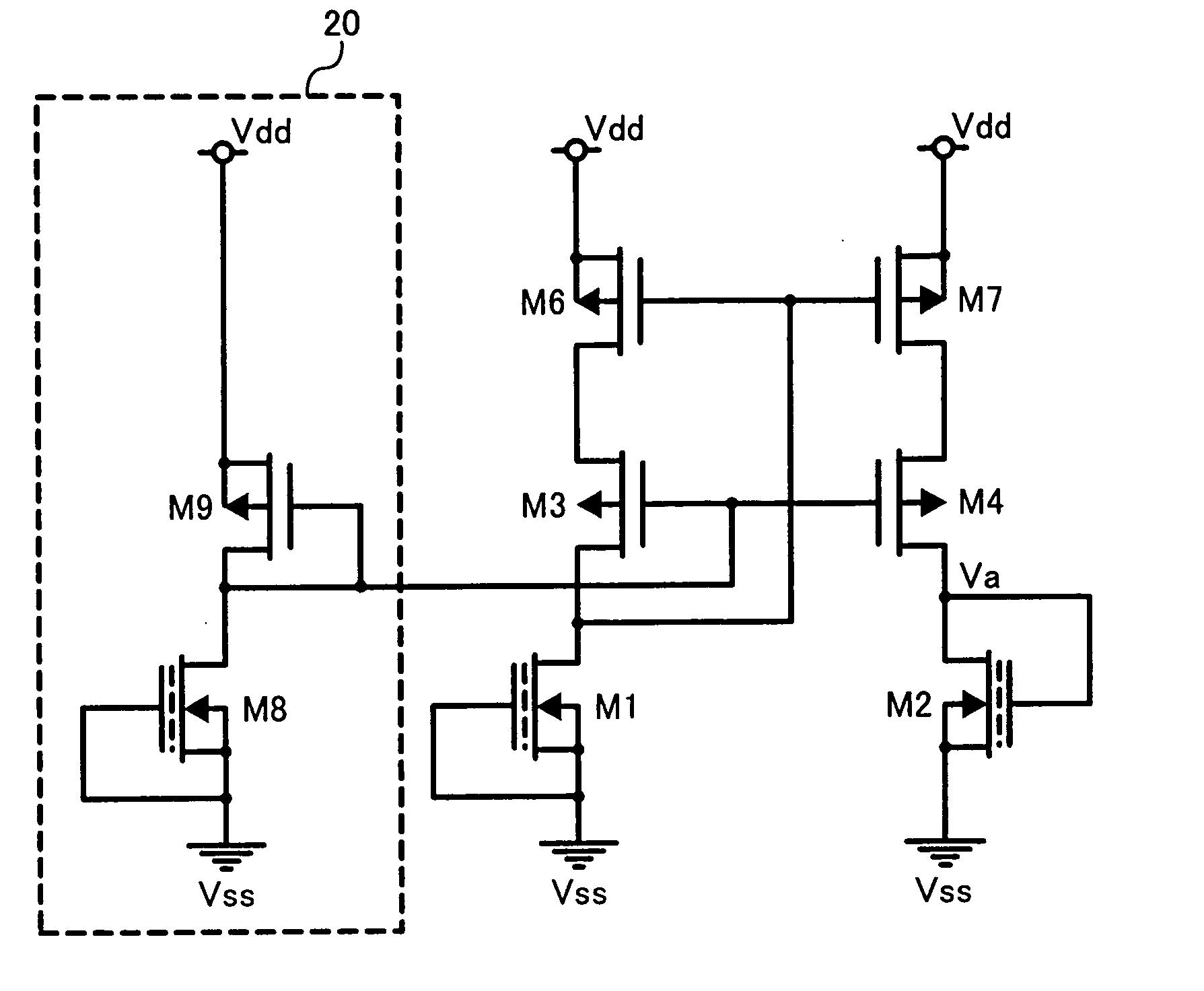
[0028]FIG. 5 illustrates an example configuration of a temperature detector circuit according to an embodiment of the present invention. Depression type N channel transistors M1 and M2 are connected in series between the second power supply terminal Vdd and the first power supply terminal Vss. A drain of the transistor M1 is connected to the ...


PUM


Abstract

A temperature detector circuit using a MOS transistor capable of reducing manufacture variation of a mobility and realizing stable output characteristics which are not affected by temperature dependency may be offered. In one example, the temperature detector circuit includes a pair of depression type transistors to output a voltage which is proportional to temperature from a connecting point of a source of a first transistor and a drain of a second transistor. The transistors are the same conducted type of current and are formed in different channel size, which are connected between power supplies in series, and have a configuration in which first transistor's gate and source are connected each other and a first transistor's drain is connected with a second power supply and second transistor's gate and drain are connected each other and a second transistor's source is connected with a first power supply.

Description

BACKGROUND OF THE INVENTION [0001] 1. Field of the Invention [0002] The present invention relates to a temperature detector circuit and an oscillation frequency compensation device using it, and more particularly to a MOS-transistor-based temperature detector circuit which has stable output characteristics and an oscillation frequency compensation device including such temperature detector circuit. [0003] 2. Discussion of the Background [0004]FIG. 1 illustrates an example of a background temperature detector circuit using a bipolar transistor with commonly connected base and collector. FIG. 2 illustrates an example of a background temperature detector circuit using a Darlington connection of bipolar transistors. [0005] The background temperature detector circuit of FIG. 1 drives the bipolar transistor by a constant current to use a temperature dependency of forward direction voltage for temperature detection. This is of the same kind as a method of using a temperature dependency of ...

Claims


Application Information

Patent Timeline
Patent Type & Authority Applications(United States)
IPC IPC(8): H01L35/00
CPCG01K7/01
Inventor YOSHIKAWA, REI
Owner RICOH KK
Why Eureka
Try Eureka