Probe array substrate and method for producing the same, and probe array and method for producing the same

a technology of probe array and substrate, which is applied in the field of probe array substrate and method for producing the same, can solve the problems of difficult detection of target molecules, insufficient detection sensitivity of target molecules, and inability to produce probe arrays having a sufficiently high packing density, so as to reduce the manufacturing variation in the amount of probe molecules held in the probe-holding portions, increase the packing density of probes on the probe array, and reduce the amount of probe molecules produced

Active Publication Date: 2010-08-26
MURATA MFG CO LTD
View PDF12 Cites 5 Cited by
  • Summary
  • Abstract
  • Description
  • Claims
  • Application Information

AI Technical Summary

Benefits of technology

[0040]According to the present invention, because the probe-holding portions are defined by recesses and the descending wall surfaces are formed between the adjacent probe-holding portions, the probe solutions to be introduced into the probe-holding portions are inhibited from spreading over the main surface, so that the packing density of the probes on the probe array can be increased.
[0041]According to the present invention, additionally, because the probe-holding portions are defined by recesses, relatively large amounts of probe solutions can be introduced into the probe-holding portions, and the probe molecules can also be held on the inner side surfaces of the recesses. Accordingly, even if the packing density is increased, as described above, the individual probe-holding portions can contain sufficient amounts of probe molecules. This eliminates the problem of insufficient detection sensitivity for target molecules due to insufficient amounts of probe molecules.
[0042]According to the present invention, additionally, variations in the amounts of probe solutions introduced into the probe-holding portions are reduced because they are strictly controlled by the shape and volume of the probe-holding portions defined by recesses, so that manufacturing variations in the amounts of probe molecules held in the probe-holding portions are reduced. As a result, manufacturing variations in the sensitivity of the probe array can be reduced.

Problems solved by technology

There is a problem, however, in that a probe array having a sufficiently high packing density cannot be produced because the spot area increases as the spotted probe solutions spread over the substrate.
If the probes hold insufficient amounts of probe molecules, it is difficult to detect target molecules because insufficient amounts of target molecules are bound to or hybridized with the probes.
However, if the packing density of the probe array is increased, the spot area is decreased, and consequently the probe spots tend to contain insufficient amounts of probe molecules, often leading to the problem of insufficient detection sensitivity for target molecules.
If the amounts of probe molecules held in the probes vary, the amounts of target molecules bound to or hybridized with the probes vary even through the concentrations of the target molecules in the solution under examination remain the same, thus leading to the problem that the concentrations of the target molecules in the solution under examination cannot be accurately determined because of varying signal strengths.
The method using spotting, however, has a problem in that the amounts of probe molecules held at the probe spots tend to vary because the amounts of probe solutions spotted on the substrate tend to vary.
The above problems are particularly serious in the production of a probe array having high packing density.

Method used


Image

  • Probe array substrate and method for producing the same, and probe array and method for producing the same
  • Probe array substrate and method for producing the same, and probe array and method for producing the same
  • Probe array substrate and method for producing the same, and probe array and method for producing the same

Examples


Embodiment Construction

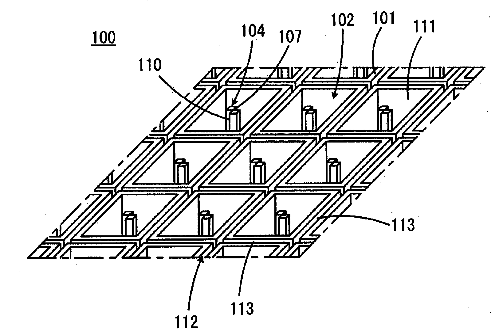
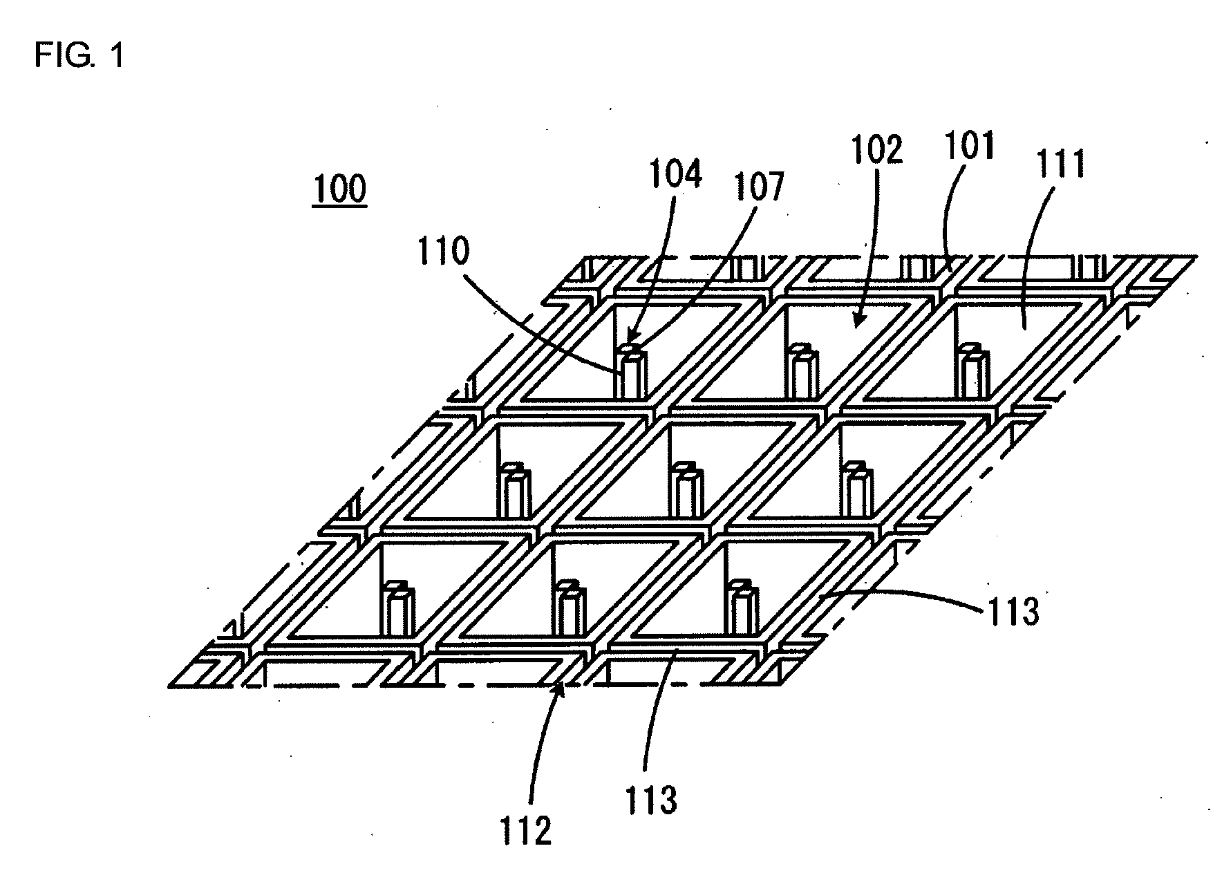
[0074]FIG. 1 is a perspective view showing part of a probe array substrate 100 according to a first embodiment of the present invention. FIG. 2 is a top view showing part of the probe array substrate 100 shown in FIG. 1.

[0075]Referring to FIGS. 1 and 2, the probe array substrate 100 has a main surface 101 and is plate-shaped as a whole. The probe array substrate 100 has a plurality of probe-holding portions 102 arranged in rows and columns along the main surface 101. The probe-holding portions 102 have an array pitch of, for example, 100 as shown in FIG. 2. The individual probe-holding portions 102 are defined by recesses in the main surface 101. In the embodiment shown, the individual probe-holding portions 102 are defined by recesses having bottom surfaces 103 at a level lower than the main surface 101. In another embodiment, the probe-holding portions can be defined by through-holes having no bottom surfaces.

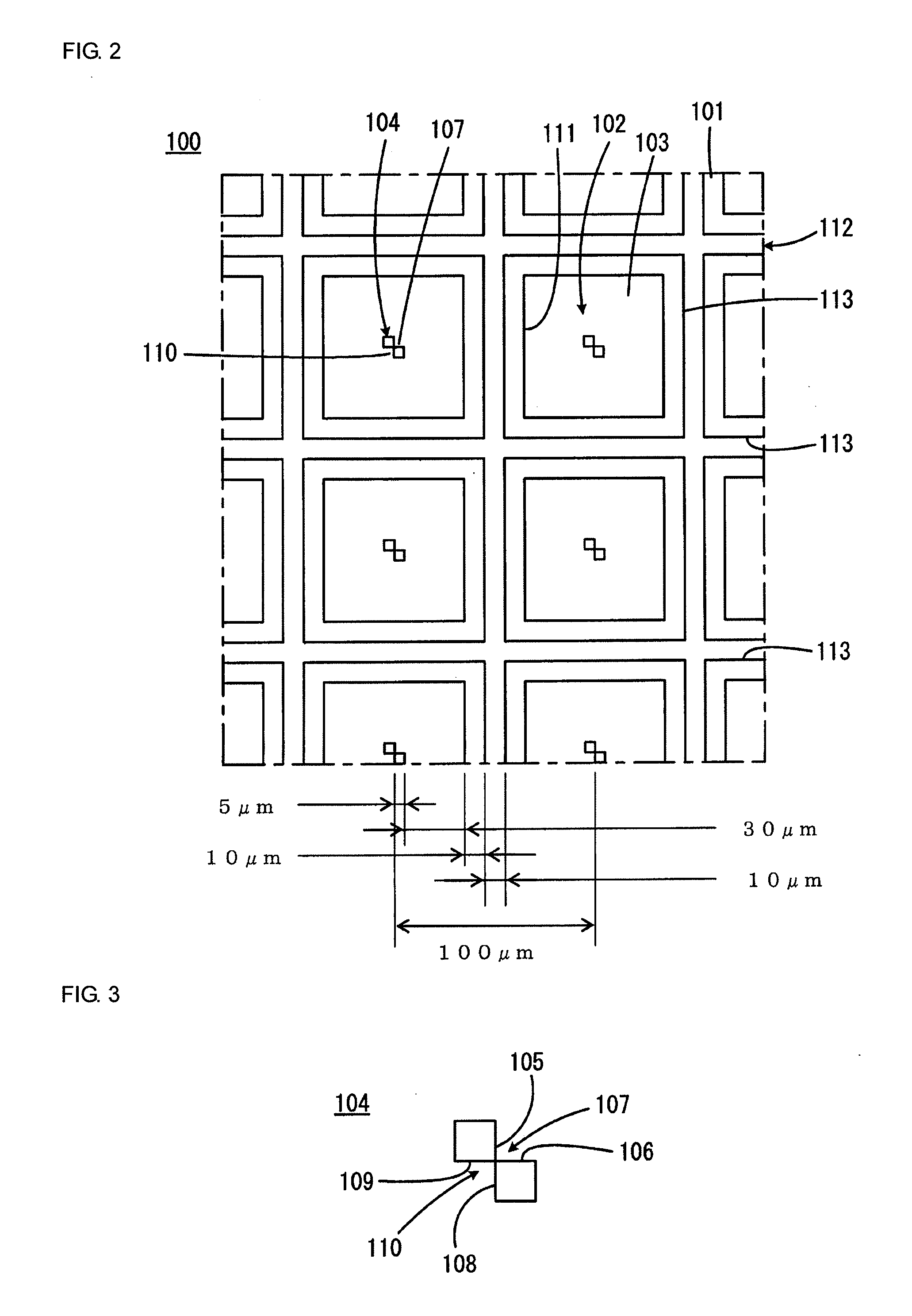
[0076]Liquid-introducing protrusions 104 are formed in the probe-holding...


PUM

PropertyMeasurementUnit
hydrophilicaaaaaaaaaa
hydrophobicaaaaaaaaaa
outer diameteraaaaaaaaaa

Abstract

A probe array substrate suitable for forming a probe array that has high packing density, that can hold sufficient amounts of probe molecules, and that has little variation in the amounts of probe molecules. A plurality of arrayed probe-holding portions are defined by recesses, and isolating grooves are formed between the adjacent probe-holding portions to prevent probe solutions introduced into the probe-holding portions from spreading to adjacent probe-holding portions. Inner surfaces of the probe-holding portions are made hydrophilic, whereas inner surfaces of the isolating grooves are made hydrophobic. Liquid-introducing protrusions are formed in the probe-holding portions.

Description

CROSS REFERENCE TO RELATED APPLICATIONS[0001]The present application is a continuation of International Application No. PCT / JP2008 / 066705, filed Sep. 17, 2008, which claims priority to Japanese Patent Application No. JP2007-302573, filed Nov. 22, 2007, the entire contents of each of these applications being incorporated herein by reference in their entirety.FIELD OF THE INVENTION[0002]The present invention relates to probe array substrates for use in the field of chemistry or biochemistry and methods for producing probe array substrates, and also to probe arrays formed using probe array substrates and methods for producing probe arrays.BACKGROUND OF THE INVENTION[0003]DNA chips have attracted attention as a tool, for example, for simultaneous genetic diagnosis for many items, simultaneous examination of many types of mRNAs for expression level, and simultaneous examination for many single nucleotide polymorphisms (SNPs). DNA chips, also called DNA microarrays, are probe arrays using...

Claims


Application Information

Patent Timeline
Patent Type & Authority Applications(United States)
IPC IPC(8): C40B40/06C40B50/08
CPCB01J2219/00317B01J2219/00373B01J2219/00387B01J2219/00619B01J2219/00621B01L3/0262G01N2035/00158B01L2200/141B01L2300/0636B01L2300/0819B01L2300/0854B01L2300/161B01L3/5085
Inventor SHIBAHARA, TERUHISA
Owner MURATA MFG CO LTD
Why Eureka
Try Eureka