
Sensor element and gas sensor

a technology of sensor element and gas sensor, which is applied in the direction of material analysis by electric/magnetic means, measurement devices, instruments, etc., can solve the problems of not being taken into consideration in the case, and the way the porosity of the plurality of leads is to be set, so as to reduce manufacturing variations

Pending Publication Date: 2021-09-30
NGK INSULATORS LTD
View PDF6 Cites 0 Cited by
  • Summary
  • Abstract
  • Description
  • Claims
  • Application Information

AI Technical Summary

Benefits of technology

The present invention provides a sensor element that can reduce manufacturing variations while suppressing an increase in oxygen concentration in the reference gas chamber. This is achieved by connecting the second porous reference electrode lead to the second pump cell, which allows oxygen pumped into the reference gas chamber to be released through pores in the second reference electrode lead. Additionally, the second reference electrode lead with higher resistance value has higher porosity than the first reference electrode lead with lower resistance value. This setup ensures that the resistance value of the second reference electrode lead is relatively small, even if there is a variation in its resistance value due to manufacturing errors. This reduces the impact on the overall resistance value of the sensor element. The gas sensor according to the present invention includes this sensor element and can achieve similar effects.

Problems solved by technology

However, how the porosities of the plurality of leads are to be set has not been sufficiently studied.
However, such a case has not been taken into consideration.

Method used


Image

  • Sensor element and gas sensor
  • Sensor element and gas sensor
  • Sensor element and gas sensor

Examples


examples

[0104]The following describes examples indicating specific examples of manufacturing a sensor element. Experimental Examples 1-1 to 6-3, 9-1, and 9-2 correspond to examples of the present invention, and Experimental Examples 7-1 to 8-3 and 9-3 correspond to comparative examples. Note that the present invention is not limited to the following examples.

Experimental Examples 1-1 to 1-3

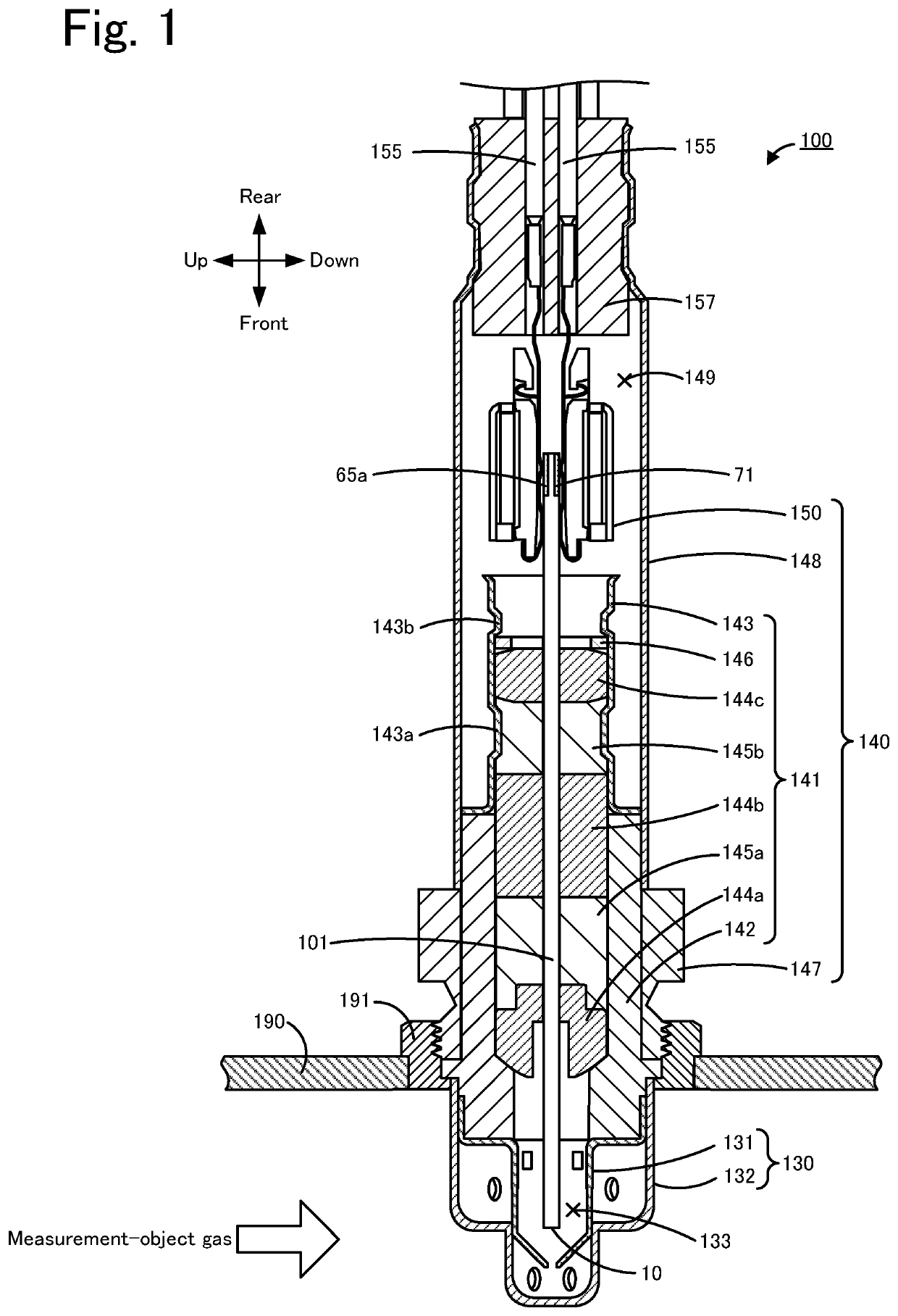
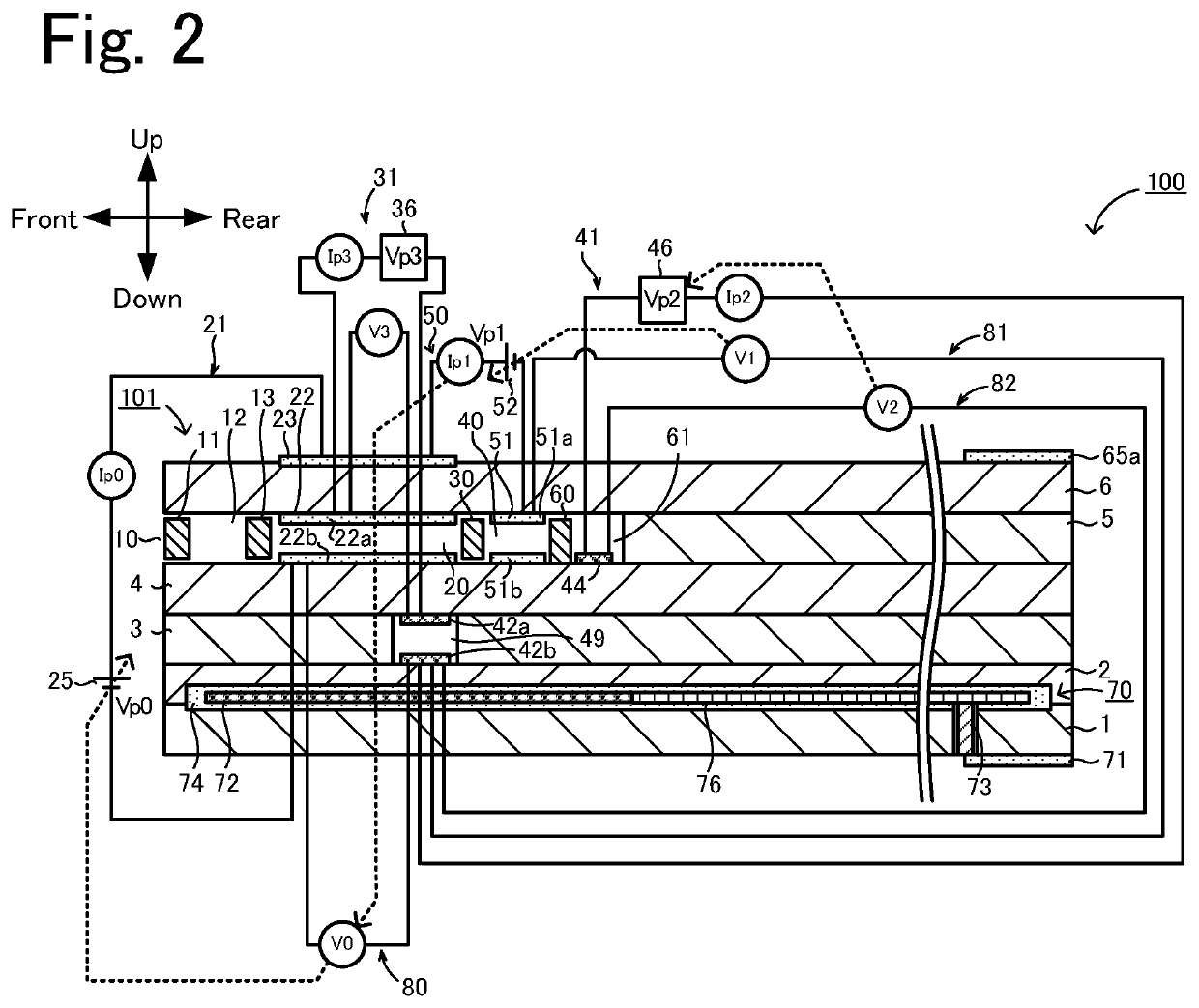
[0105]In Experimental Example 1-1, the sensor element 101 of the gas sensor 100 illustrated in FIGS. 1 and 2 was produced by using the manufacturing method described above. In the production of the sensor element 101, the ceramic green sheets were formed by tape casting of a mixture of zirconia particles containing 4 mol % yttria as a stabilizer with an organic binder, a dispersing agent, a plasticizer, and an organic solvent. The first and second reference electrodes 42a and 42b were porous cermet electrodes composed of Pt and zirconia. The patterns for the first and second reference electrodes 42a and 4...

experimental examples 2 to 9

[0106]In Experimental Examples 2 to 9, the sensor element 101 was manufactured in the same way as that in Experimental Example 1, except that the proportion of the pore-forming agent in the platinum paste for forming the lead 38b and the lead 48b is changed to variously change the porosities P1 and P2 in the manner as shown in Table 1. In each of Experimental Examples 2 to 9, three sensor elements 101 were produced under the same manufacturing conditions. That is, a total of 24 sensor elements 101 were produced for Experimental Examples 2-1 to 2-3, 3-1 to 3-3, 4-1 to 4-3, 5-1 to 5-3, 6-1 to 6-3, 7-1 to 7-3, 8-1 to 8-3, and 9-1 to 9-3.

[0107][Confirmation of Presence of Break in Lead]

[0108]For each of a total of 27 sensor elements 101 in Experimental Examples 1-1 to 9-3, the presence of a break in the leads 38b and 48b was examined. The presence of a break in the lead 38b was confirmed by examining electrical conduction between the connector electrodes 65a and 65b by using a tester. T...


PUM

PropertyMeasurementUnit
porosity P2aaaaaaaaaa

Abstract

A sensor element includes a first pump cell including a first pump electrode and a first reference electrode, a first pump circuit including the first pump cell and a first reference electrode lead, a second pump cell including a second pump electrode and a second reference electrode and a second pump circuit including the second pump cell and a second pump electrode. A resistance value R2 of the second pump circuit is higher than a resistance value R1 of the first pump circuit, and a porosity P2 of the second reference electrode lead is higher than a porosity P1 of the first reference electrode lead.

Description

[0001]The application claims priority to Japanese Patent Application No. 2020-058666 filed in the Japan Patent Office on Mar. 27, 2020, the entire contents of which are incorporated herein by reference.BACKGROUND OF THE INVENTION1. Field of the Invention[0002]The present invention relates to a sensor element and a gas sensor.2. Description of the Related Art[0003]Sensor elements are known in the related art for detecting a specific gas concentration such as a NOx concentration in a measurement-object gas such as an exhaust gas of an automobile (e.g., PTLs 1 and 2). PTL 1 describes a sensor element including an element body including solid electrolyte layers, a first measurement chamber and a second measurement chamber disposed inside the element body, a detection electrode disposed in the first measurement chamber, a pumping electrode disposed in the second measurement chamber, a reference oxygen chamber disposed inside the element body, and a reference electrode and a pumping elect...

Claims


Application Information

Patent Timeline
Patent Type & Authority Applications(United States)
IPC IPC(8): G01N27/41G01N33/00
CPCG01N27/41G01N33/0037G01N27/417G01N27/4076Y02A50/20G01N27/4062
Inventor WATANABE, YUSUKENIIZUMA, SHOTARO
Owner NGK INSULATORS LTD
Learn More