System and method for measuring scene reflectance using optical sensors

a technology of optical sensors and reflectance, applied in the field of measuring scene reflectance, can solve the problems of difficult inverse light transport problem in scene analysis using camera images, bandwidth limits resolution as well as frame rate, and extremely expensive high-speed cameras pose several problems in terms of scalability, so as to achieve fast and accurate attribute measurement, high speed and accuracy

Inactive Publication Date: 2007-11-22
MITSUBISHI ELECTRIC RES LAB INC
View PDF13 Cites 71 Cited by
  • Summary
  • Abstract
  • Description
  • Claims
  • Application Information

AI Technical Summary

Benefits of technology

[0030]Rapid advances in solid state lighting and sensing have made possible the exploration of new scene capture techniques for computer graphics and computer vision. The high speed and accuracy of recently developed light emitters and photo sensors enable very fast and accurate attribute measurement even for highly dynamic scenes.

Problems solved by technology

However, analyzing scenes using camera images is known to be a difficult inverse light transport problem, because the radiance measured at each camera pixel is a complex function of geometry, illumination, and reflectance.
However, the extremely expensive high-speed cameras pose several issues in terms of scalability.
Bandwidth limits the resolution as well as the frame-rate.
However, scene factorization is an ill-posed problem and solutions require assumptions regarding the reflectance variation in the scene and / or the illumination variation due to the light source.
Typically, there is a tradeoff in complexity of the emitter, the receiver and bandwidth.
It is difficult to achieve high-speed scene capture with low-cost, simple devices.

Method used


Image

  • System and method for measuring scene reflectance using optical sensors
  • System and method for measuring scene reflectance using optical sensors
  • System and method for measuring scene reflectance using optical sensors

Examples


Embodiment Construction

System and Method Overview

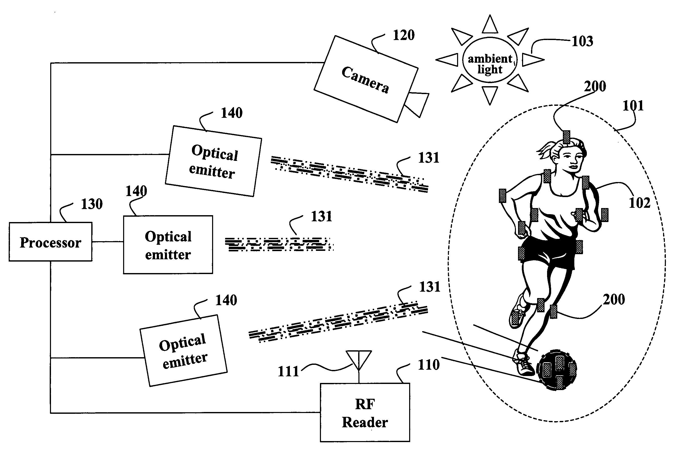
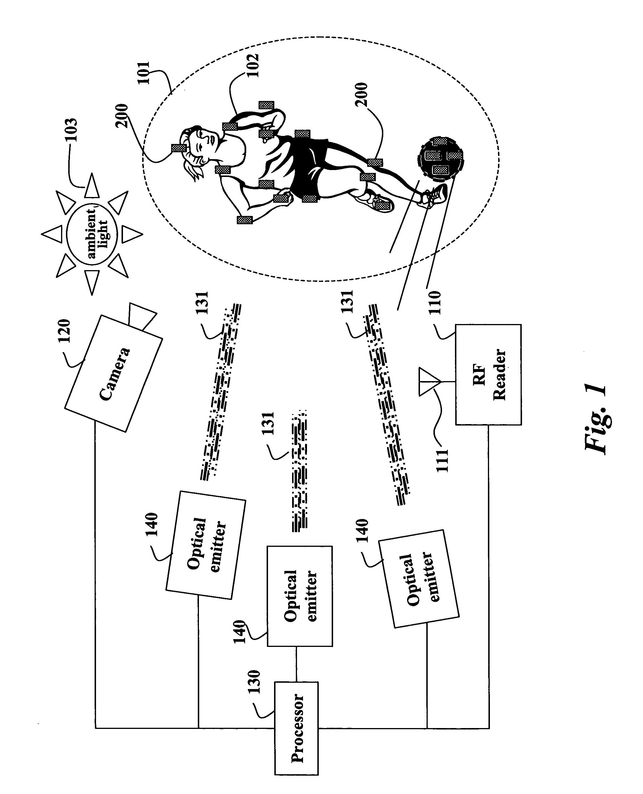
[0042]FIG. 1 shows a system and method for factorizing a scene 101 according to one embodiment of our invention. The system can include one or more optical tags 200 arranged in a scene 101. The tags can be mounted on a moving object 102 or static objects, not shown. The system also includes optical emitters 140. Optionally, the system can also include a radio frequency (RF) reader 110 with an antenna 111, and a camera 120 all connected to a processor 130. The optical emitters are in the form of light emitting diodes that emit spatio-temporally modulated infrared light 131.

[0043]The scene 101 can be illuminated by ambient lighting 103, indoor or outdoor. However, it is important to note that, unlike conventional camera based tracking, the invention can also operate in the dark because infrared light is used to illuminate the tags 200. Because a camera is not used to locate the tags as in conventional computer vision systems, challenging ambient light conditi...


PUM

PropertyMeasurementUnit
wavelengthaaaaaaaaaa
reflectanceaaaaaaaaaa
incident energyaaaaaaaaaa

Abstract

A system measures reflectance in a scene. A first optical sensor is configured to measure incident energy at a location in a scene. A second optical sensor is configured to measure reflected energy from the location in the scene. The incident energy and the reflected energy are analyzed to determine a photometric property at the location of the scene.

Description

RELATED APPLICATIONS[0001]This application is related to U.S. patent application Ser. No. ______, “System and Method for Sensing Geometric and Photometric Attributes of a Scene with Multiplexed Illumination and Solid State Optical Devices” and U.S. patent application Ser. No. ______, “Apparatus and Method for Illuminating a Scene with Multiplexed Illumination for Motion Capture,” both of which were co-filed with this application by Raskar et al. on May 17, 2006.FIELD OF THE INVENTION[0002]This invention relates generally to measuring scene reflectance, and more particularly to measuring reflectance in a scene and setting camera parameters accordingly.BACKGROUND OF THE INVENTION[0003]A major trend in illumination is solid-state lighting that uses light emitting diodes (LEDs). As LEDs begin to replace incandescent and fluorescent lamps, LEDs can be used for multiplexed optical communication with intelligent devices in addition to providing illumination. Solid-state optical emitters ar...

Claims


Application Information

Patent Timeline
Patent Type & Authority Applications(United States)
IPC IPC(8): G01J1/42G01N21/47
CPCG01J1/42G01N21/55G06T2207/30204G06T7/0042G06T2207/10016G01N2021/557G06T7/73
Inventor RASKAR, RAMESHNII, HIDEAKIZHAO, YONGDIETZ, PAUL H.BRUNS, ERICH
Owner MITSUBISHI ELECTRIC RES LAB INC
Why Eureka
Try Eureka