[0014]Oppositely to the above case, when controlling a controlled object the controlled variable of which has a local minimum value which it takes as the control input is varied, insofar as the target value is set to a value not smaller than the local minimum value, it is possible to cause the controlled variable to converge to the target value with accuracy. On the other hand, even when the target value is set to a value smaller than the local minimum value, assuming that as the control input is varied, the controlled variable changes past the local minimum value, the correlation between the control input and the controlled variable once increases and then decreases again, and simultaneously, there occurs a change from one of the positive and negative correlations to the other, so that the correlation parameter represents such a change in the correlation. Therefore, by determining the increasing / decreasing direction of the control input according to the correlation parameter, it is possible to maintain the controlled variable at the local minimum value or in its vicinity, whereby both the control stability and control accuracy can be maintained at a high level. As described above, even when controlling the controlled object having extremal characteristics, by determining the increasing / decreasing direction of the control input according to the correlation parameter, it is possible to provide control such that the controlled variable becomes equal to the target value when the target value is in a range which the controlled variable can attain, whereas when the target value is outside the range which the controlled variable can attain, it is possible to maintain the controlled variable at a value closest to the target value within the attainable range, i.e. a value in the vicinity of the extremum value, whereby both the control stability and the control accuracy can be maintained at a high level. In addition thereto, if both the increasing / decreasing rate and the increasing / decreasing direction are determined according to the correlation parameter, it is possible to obtain all the advantageous effects described above.
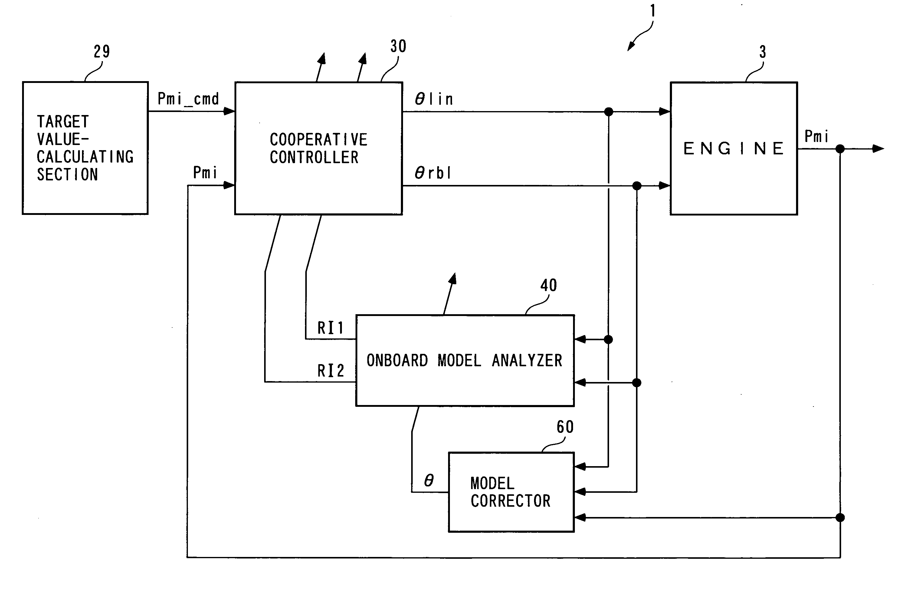
[0015]Further, the controlled object model is corrected such that the controlled variable of the controlled object model matches the controlled variable of the controlled object, and hence even when the modeling error occurs due to the variation between individual units of the controlled object and the aging of the same, it is possible to quickly accommodate the modeling error, and increase the accuracy of calculation of the correlation parameter. As a result, it is possible to improve the control accuracy. (It should be noted that throughout the specification, “calculation”, “determination”, “setting”, and “correction” as in “calculation of the correlation parameter”, “calculation or determination of the control input”, “setting of the target value”, and the correction of the controlled object model” are not limited to execution of computation, determination, setting, and correction by a program, but include generating electric signals representative of them.)
[0016]Preferably, the model corrector means calculates a plurality of correction parameters for use in correction of the controlled object model, in a manner associated with a plurality of regions obtained by dividing a region where the control input is variable respectively, and calculating ones of the correction parameters corresponding to ones of the regions where the calculated control input exists, with a predetermined second
control algorithm, such that the controlled variable of the controlled object model matches the controlled variable of the controlled object.
[0017]With this configuration of the preferred embodiment, a plurality of correction parameters for use in correcting the controlled object model are calculated in a manner associated with a plurality of regions formed by dividing a region within which the control input is variable, and ones of the correction parameters corresponding to ones of the regions in which the control input exists are calculated with a predetermined second
control algorithm such that the controlled variable of the controlled object model matches the controlled variable of the controlled object. Therefore, even when the modeling error is different between the regions, it is possible to correct the controlled object model on a region-by-region basis using such correction parameters respectively associated with the regions. As a result, differently from the prior art, even in the cases where the controlled object model cannot be expressed using a recurrence formula, where the controlled object has characteristics suffering from a local error or aging in a certain one of the regions, or where the controlled object has characteristics which vary among the regions, it is possible to cause the controlled object model to properly match the actual characteristics of the controlled object. As a result, in controlling such a controlled object, when a modeling error occurs due to variation between individual units of the controlled object and aging of same, it is possible to compensate for the modeling error, and improve the robustness of the control apparatus against the modeling error. This makes it possible to further improve the control accuracy. In addition thereto, differently from the conventional cases where the sequential least-squares method is used for the identification algorithm, it is not necessary to add an oscillating input to the control input so as to satisfy self-exciting conditions, which makes it possible to further improve the control stability, more specifically, the degree of convergence (setting properties) of the controlled variable to the target value.
[0018]More preferably, the predetermined second control algorithm includes a predetermined response-specifying control algorithm.
[0019]With the configuration of this preferred embodiment, the correction parameters are calculated with an algorithm including a predetermined response-specifying control algorithm, such that the controlled variable of the controlled object model matches the controlled variable of the controlled object. Therefore, even in the case of controlling a non-linear controlled object the controlled object model of which cannot be expressed using a recurrence formula, it is possible to calculate the correction parameters as values that do not cause an unstable behavior, such as an oscillating behavior or overshooting, and using the correction parameters thus calculated, it is possible to control the controlled object while correcting the controlled object model. As a result, it is possible to prevent the
transient response of the
control system from becoming oscillatory or unstable, and improve the control accuracy during a transition period.

