Spanner

a ratchet mechanism and spanner technology, applied in the field of spanners, can solve the problems of reducing working efficiency, difficult manufacturing, and inability to use spanners with ratchet mechanisms, and achieve the effects of easy tightening or releasing, large thickness or width, and rarely to be rusty or broken

Inactive Publication Date: 2007-11-29
SHINANO KENSHI
View PDF11 Cites 4 Cited by
  • Summary
  • Abstract
  • Description
  • Claims
  • Application Information

AI Technical Summary

Benefits of technology

[0018] A spanner of the present invention as described above has following advantages. The construction of the first and the second jaws does not have a large thickness or width, so that a bolt (or nut) placed in a narrow gap is also easily tightened or released. Moreover, the tension spring is installed on the interior of the jaw, the tension spring is rarely to be got rusty or broken by external impact and keep rust-preventing and lubricating oil within the long hole for a long period, which increases the durability of the spanner. The guiding operation of the convex guidance part of the elastic support plate enables a bolt to be easily gripped when gripping a bolt. Also, the elastic support plate elastically compress the gripped bolt so that the spanner is not easily separated from the bolt when rotating the lever, which improves the working efficiency for tightening and releasing of the bolt or nut.

Problems solved by technology

However, if only a narrow gap is allowed for operation of tightening a bolt, the ratchet spanner is not applicable due to the heavy thickness of the socket in spite of the convenience of the ratchet spanner, then a user has to use a flat spanner.
But, the user has to endure the inconvenience to repeatedly insert the bolt in the jaws of the spanner once rotating the spanner at a certain degrees, which has a problem to greatly decrease the working efficiency.
However, these conventional spanners have a common problem that the manufacturing is difficult due to the complex construction and structure of the ratchet mechanism installed for rotating in one direction.
Moreover, the jaws for gripping the bolt have too large volume, therefore the spanner with a ratchet mechanism can't be used if only a narrow gap is allowed for operation for tightening a bolt.
This automatic spanner solves the above problem partly, but it has a problem that the toggle bar is extruded beyond the outside surface of the jaw so that the width(the distance between the outside surfaces of two jaws) becomes too large, therefore it can't be used when only a narrow gap in width is allowed for operation for tightening the bolt.
Moreover, it is difficult to adjust the tension of the torsion spring supporting the toggle bar, so that the friction force of the toggle bar against the bolt can't be adjusted appropriately to working conditions, which frequently decreases the working efficiency.
Also, it has another problem that the rear end of the toggle bar is extruded to the exterior so that it is easily broken by the external impact, and the torsion spring supporting the toggle bar is exposed to the exterior, so that it is also easily got rusty or broken by the external impact, thus the durability of the spanner is shortened.

Method used


Image

  • Spanner
  • Spanner
  • Spanner

Examples


first embodiment

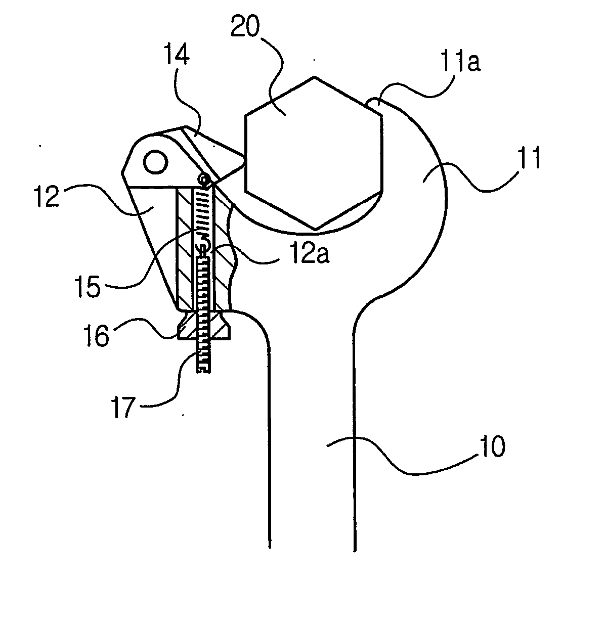
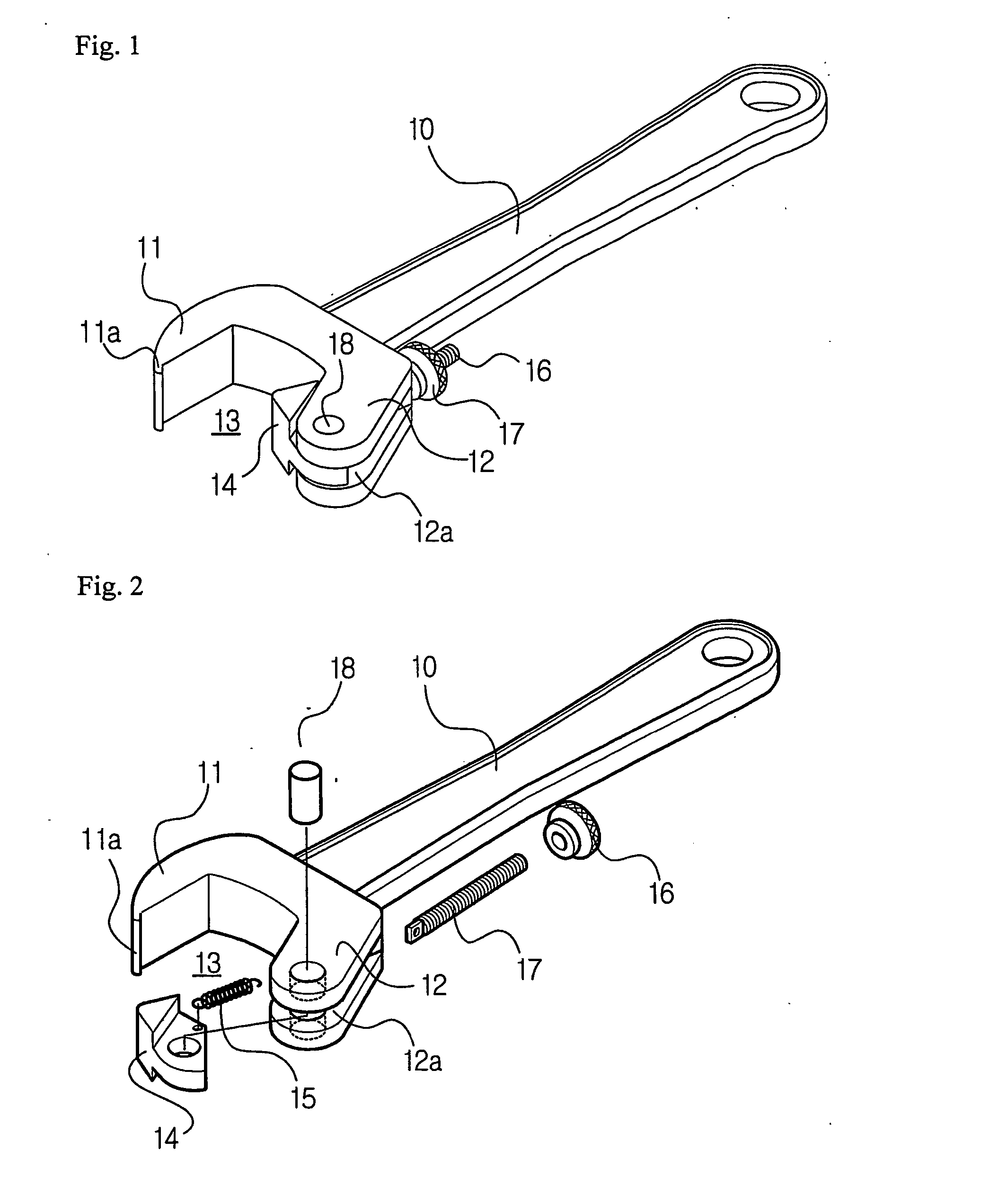
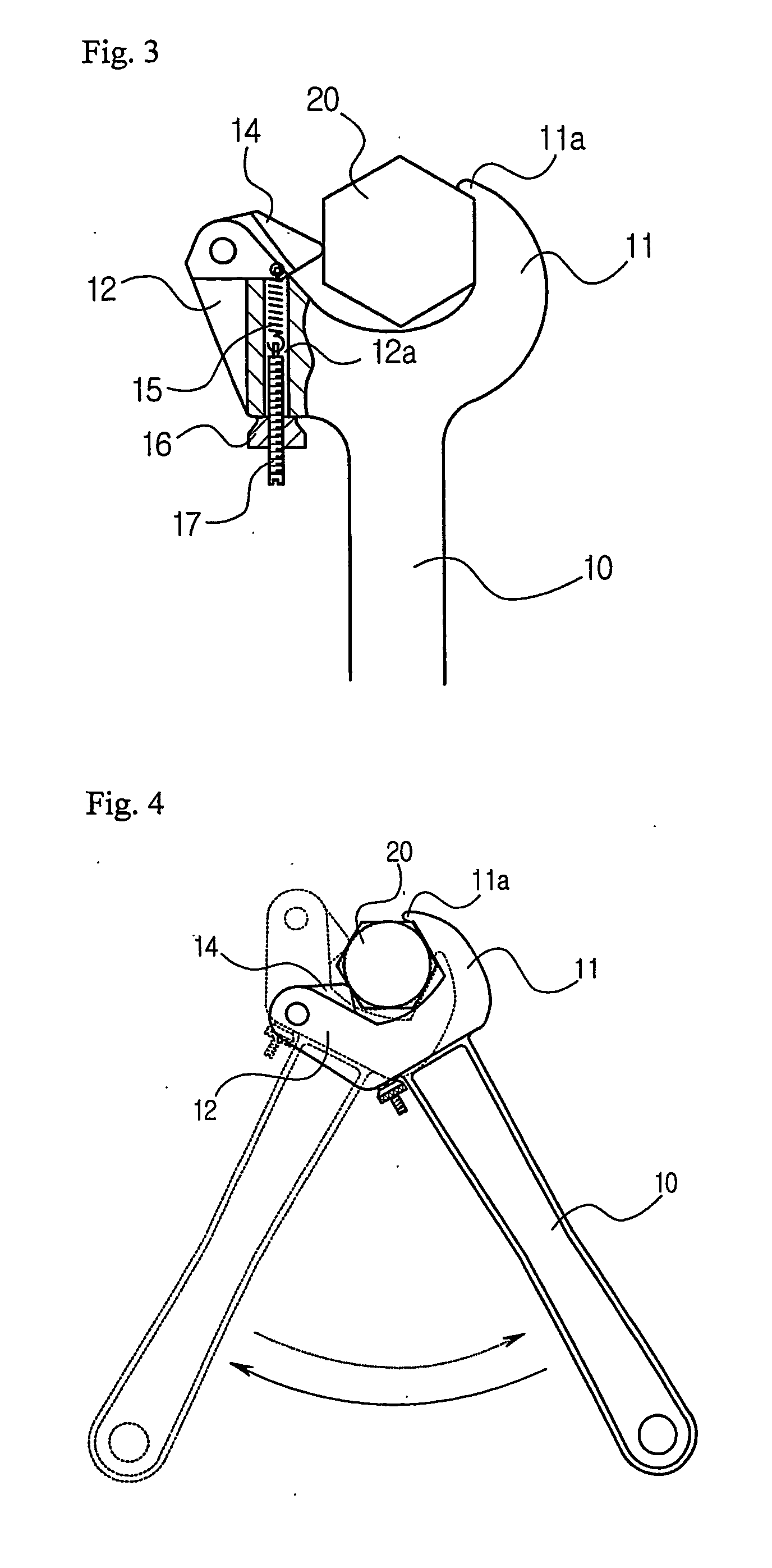
[0029]FIG. 1 is a perspective view of the spanner according to the present invention, and FIGS. 2 and 3 are respectively an exploded perspective view and a cross-sectional view thereof.

[0030] As shown in the drawings, the spanner according to the present invention comprises a lever (10) in a shape of stick as a handle; a first jaw and a second jaw (11,12) respectively extending from both sides of the lead end of the lever and forming a gripping space (13) therebetween for gripping a bolt (20); a toggle bar (14) installed on the lead end of the second jaw so as to be allowed to be rotated only toward outward of the gripping space; a tension adjustment bolt (16) engaged with the long hole (12b) longitudinally formed on the bottom of the second jaw from the outer surface of the second jaw; a tension adjustment nut (17) for supporting the tension adjustment bolt (16) from the outside of the second jaw (12); and a tension spring (15) for connecting the middle part of the inner side of th...

second embodiment

[0035]FIG. 5 is a perspective view of the spanner according to the present invention, and FIGS. 6 and 7 are respectively an exploded perspective view and cross-sectional view thereof.

[0036] As described in the drawings, the spanner according to the second embodiment of the present invention comprises, a lever (10); a first jaw and a second jaw (11,12) extending from the lead end of the lever (10) to form a gripping space (13) therebetween; a toggle bar (14) rotatably hinged on the lead end of the second jaw so as to be allowed to be rotated only to outward of the gripping space; a tension adjustment bolt (16) engaged with a long hole (12b) longitudinally formed on the second jaw (12) from the outer surface of the second jaw, and a tension adjustment nut (17) connected to the rear end of the tension adjustment bolt (16) from the outside of the second jaw (12); a tension spring (15) connected to the lead end of the tension adjustment bolt (16) for elastically supporting the toggle bar...


PUM


Abstract

The present invention relates to a spanner having a toggle bar installed in at least a jaw and allowed to be rotated in one direction for tightening or releasing a bolt (or nut) continually by continuous operation of rotating the spanner's lever in one and converse directions repeatedly in a state of gripping the bolt, also easily operative for tightening or releasing a bolt (or nut), especially, placed in a narrow gap. The spanner is constructed to comprises a lever; a first jaw and a second jaw respectively extending from both sides of the lead end of the lever and forming a gripping space therebetween for gripping a bolt; a toggle bar installed on the lead end of the second jaw to be allowed to be rotated only to outward of the gripping space; a tension adjustment bolt installed in the long hole formed on the bottom of the second jaw and having a lead end connected to the inner side of the toggle bar so as to elastically support the toggle bar to inward of the gripping space.

Description

TECHNICAL FIELD [0001] The present invention relates to a spanner having a toggle bar installed on at least a jaw to be allowed to be rotated only in one direction for tightening or releasing a bolt (or nut) by continuous operation of pivoting the lever of the spanner in one and converse directions repeatedly in a state of gripping the bolt. BACKGROUND ART [0002] Spanners are the most representative fastening tools for tightening or releasing a bolt or nut etc. operated by using a leverage of the gripping lever in a shape of stick. Generally, a spanner is constructed to have a gripping lever in a shape of stick, and two jaws extending respectively from the lead end of the lever. When a bolt (or nut) is inserted in a gripping space formed between the two jaws, the bolt is tightened or released by rotating the lever while applying force to the lead end of the lever using the leverage exerted in proportion to the length of the lever. [0003] At present, there are used many kinds of span...

Claims


Application Information

Patent Timeline
Patent Type & Authority Applications(United States)
IPC IPC(8): B25B13/10B25B13/08B25B13/46
CPCB25B13/46B25B13/08
Inventor CHOI, OCK-SOON
Owner SHINANO KENSHI
Why Eureka
Try Eureka