Lubricating system for a vehicle power unit

Inactive Publication Date: 2007-11-29
HONDA MOTOR CO LTD
View PDF58 Cites 22 Cited by
  • Summary
  • Abstract
  • Description
  • Claims
  • Application Information

AI Technical Summary

Benefits of technology

[0012]According to the lubricating system for a vehicle power unit of the present invention configured as above, the intermediate shaft, which constitutes a portion of the transmission, is supported on the bisected type power unit case, and the axial oil passage formed to establish communication between respective opposed ends of the intermediate shaft communicates with the oil passages formed in the first and second case halves. Therefore, communication between the oil passages in the halves of the power unit case can be established through the axial oil passage, and the lubricating oil can be jetted into the inside of the power unit case. By thus utilizing component members of the transmission for oil passages, a dedicated pipe member for exclusive use as a lubrication passageway, as adopted in the prior art, can be omitted, whereby reductions in size, weight and cost of a transmission are obtained.
[0013]In addition, when the intermediate shaft is borne on the power unit case while keeping the condition where a tip portion of the anti-rotation member projecting radially outwards from the intermediate shaft is fitted in the lock hole in the inside wall surface of the power unit case, the rotation of the intermediate shaft is accurately restricted with this simple structure, and the intermediate shaft is accurately positioned in the circumferential direction in relation to the power unit case. Therefore, when the direction in which the radial oil passage exte

Problems solved by technology

According to the above described known lubricating system, the transmission can be effectively lubricated because the lubricating oil is jetted to the meshing portions of the gears, but, on the other hand, the dedicated pipe member is used exclusively to form the oil passage, so that the number of component parts is increased, resulting a compli

Method used


Image

  • Lubricating system for a vehicle power unit
  • Lubricating system for a vehicle power unit
  • Lubricating system for a vehicle power unit

Examples


Example

[0034]A selected illustrative embodiment of the invention will now be described in some detail, with reference to the drawings. It should be understood that only structures considered necessary for clarifying the present invention are described herein. Other conventional structures, and those of ancillary and auxiliary components of the system, are assumed to be known and understood by those skilled in the art. In the drawings, the directions of arrow U and arrow F indicate the upper side and the front side, respectively.

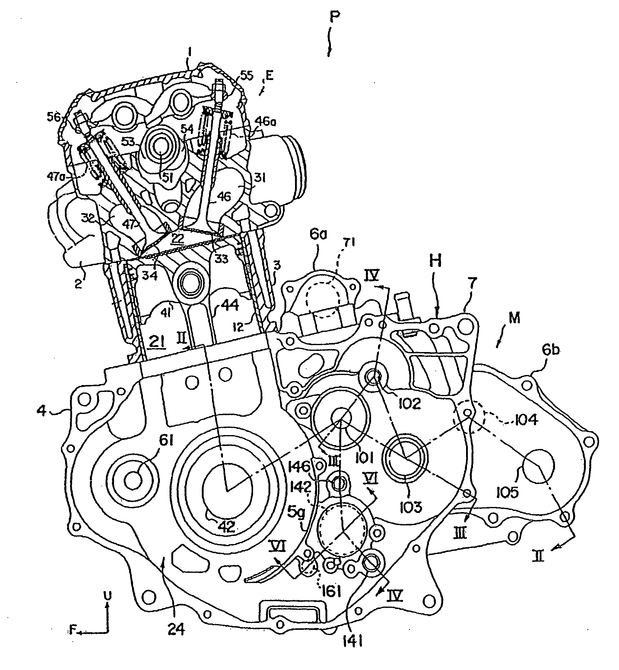
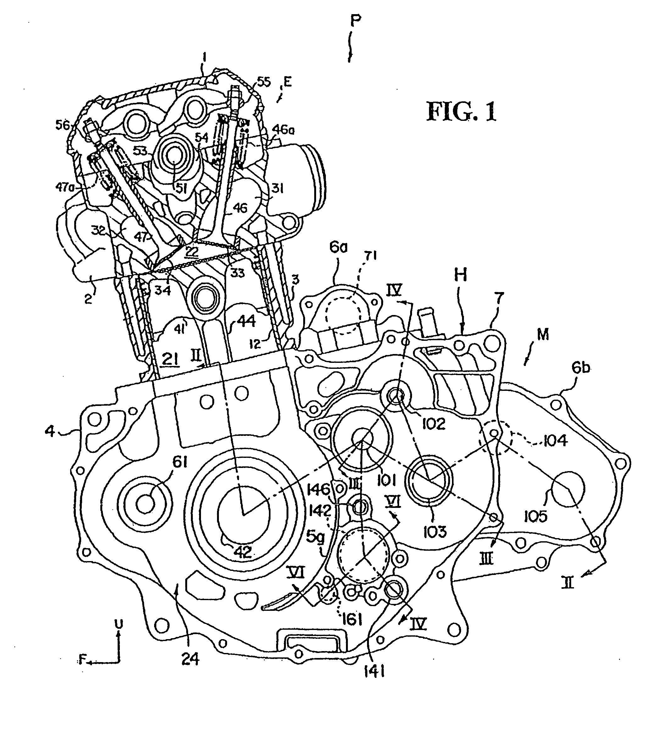
[0035]FIG. 1 shows a left side sectional view of a power unit P of a saddle-ride type vehicle provided with a lubricating system according to the present invention. Incidentally, a saddle-ride type vehicle refers to a vehicle on which a rider / operator straddles the vehicle during operation. Examples of the saddle-ride type vehicle include, but are not limited to, an all-terrain vehicle, a motorcycle, a jet ski, and the like. The power unit P consists of a single-cyl...


PUM


Abstract

A lubricating system for a vehicle transmission is provided by which the transmission is effectively lubricated, without increasing the number of component parts. The transmission includes an input shaft, an intermediate shaft and an output shaft, each of which are contained in the inside of a power unit case. The intermediate shaft has with an axially extending oil passage that establishes communication between both opposed ends of the intermediate shaft such that one end of the intermediate shaft permits communication between the axial oil passage and a first oil passage formed in a first case half, and a second end of the intermediate shaft permits communication between the axial oil passage and a second oil passage formed in a second case half. The intermediate shaft also includes radial oil passages extending radially outward from the axial oil passage and opening in an outer peripheral surface thereof.

Description

CROSS-REFERENCE TO RELATED APPLICATIONS[0001]The present invention claims priority under 35 USC 119 based on Japanese patent application No. 2006-146730, filed on May 26, 2006. The subject matter of this priority document is incorporated by reference herein.BACKGROUND OF THE INVENTION[0002]1. Field of the Invention[0003]The present invention relates to a lubricating system for a vehicle power unit, the power unit including an internal combustion engine and a transmission, the transmission modifying the rotational speed of the engine and transmitting the rotational driving force of the engine to vehicle wheels.[0004]2. Description of the Background Art[0005]Known vehicle transmissions include a plurality of gear trains which are selectively engagable and are disposed between an input shaft and an output shaft arranged in parallel to each other. In addition, in a power unit including an internal combustion engine and a transmission, in order to obtain stable operation of the internal ...

Claims


Application Information

Patent Timeline
IPC IPC(8): F01M1/02F01M1/04F02B75/32F16H3/089F16H57/02F16H57/04
CPCF16H57/0426F16H57/043F16H2057/02065F16H2057/0203F16H57/0494
Inventor NISHI, TORUIINO, KAZUAKI
Owner HONDA MOTOR CO LTD
Why Eureka
Try Eureka