Hydraulic downhole oil recovery system

a hydraulic and oil recovery technology, applied in the direction of fluid removal, gearing, borehole/well accessories, etc., can solve the problems of inability to achieve, limited oil recovery depth and volume, and hampered conventional oil recovery systems, so as to reduce the efficiency of hydraulic fluid, avoid power loss, and improve the effect of operation efficiency

Inactive Publication Date: 2007-11-29
CRAWFORD JOE
View PDF39 Cites 0 Cited by
  • Summary
  • Abstract
  • Description
  • Claims
  • Application Information

AI Technical Summary

Benefits of technology

[0048] As mentioned, Applicant's invention circulates a water-based fluid, rather than hydraulic fluid, throughout the system. This substitution promotes both the novel design and great efficiency of the present invention. More specifically, the use of water-based fluid provides for a much greater operating efficiency. That is, typical hydraulic fluid is compressible and therefore requires a significantly greater number of pump strokes to “pressure up” than a column of water-based fluid. As a result, the efficiency of hydraulic fluid decreases over any appreciable distance as its compression causes wasted pump strokes, which directly translates to lost power. Because the present system uses incompressible water-based fluid, problems associated with fluid compressibility have been eliminated. Specifically, power loss is avoided as there is no appreciable loss in efficiency due to the compression of the circulated production fluid.
[0049] Other useful embodiments of the invention are thought to utilize additives that my increase the viscosity of the water-based hydraulic fluid. Such may involve the use of “oils” to form emulsions. These embodiments are thought to be particularly useful in further reducing fluid friction and further improving operating efficiency.
[0050] However, the benefits associated with the present system do not end with use of water-based fluid. The novelty of the present invention further lies in the placement and action of the downhole pump. The downhole pump is placed below the production oil, as such, the surface unit is in a mechanically superior alignment. That is, the surface unit is responsible for actuating only the downhole pump, rather than cycling the entire production string through the production tube. This feature alone, and in conjunction with an efficient surface unit, provides for an extreme decrease in the energy used during production.
[0051] Additionally, devices of the past have not been successful in using coil tubing, as it has proven too difficult to incorporate such tubing within the production tube itself. However, Applicant has cleared that hurdle. The present system provides for the coil, flexible tubing contained within the production tube all the while circulating water-based fluid from the surface to the downhole pump unit. This feature alone, and particularly in combination with coil production tubing, allows the present invention to be useful in deviated wells that would otherwise be inaccessible.

Problems solved by technology

Conventional oil recovery systems are hampered by limitations on both the depth and volume of oil that can be recovered.
Moreover, particular embodiments of the present invention allow certain embodiments of the system to be maintained on solar energy, which is not feasible with known downhole oil recovery systems.
Conventional oil recovery systems are relatively short-lived and require a high level of maintenance in view of the present device.
Current systems rely on large, cumbersome parts that are prone to leaking and causing wear and tear of standard production tubing.
A large portion of the problems associated with known oil recovery systems come from the secured-production tubing configuration of those systems.
Specifically, reciprocation of the sucker rod within the production tube causes wear and tear of the tubing.
As a result, leaks often originate within the tubing at the secured reciprocation location.
This leads to both inefficiency and environmental contamination.
Common oil recovery systems also present significant problems at the surface.
Surface pumps are loud, cumbersome, visually offensive, dangerous, and environmentally unfriendly.
As such, restrictions are placed on both where and when these systems can be used.
Prohibitive zoning restrictions are often based on the way the pumps look, how they sound, and the inconvenience they cause to people in their proximity.
Further, it is widely known in the art that conventional surface pumps are prone to leaking both oil and hazardous fumes.
As such, environmental concerns are very high and periodic maintenance is required, all the while cost of operation increases while efficiency decreases.
Surface pumps are also dangerous; each year, injuries and deaths result from the operation of such pumps.
These casualties often involve children who make their way to the pumps, drawn by curiosity, only to get caught in the moving parts.
Yet, of these known systems, none are believed to be operative in reality, and at best are not able to match the advantages provided by Applicant's invention.
Traditional oil well pump devices can only pump oil to the surface during an upstroke.
Coil tubing is known in the industry and is typically used to clean sand from well bores; however, no known products have been able to incorporate such tubing to transfer power fluid and provide housing for system components.
In the past, fitting system components and power fluid tubing within coil tubing has proven to be too difficult.

Method used


Image

  • Hydraulic downhole oil recovery system
  • Hydraulic downhole oil recovery system
  • Hydraulic downhole oil recovery system

Examples


Embodiment Construction

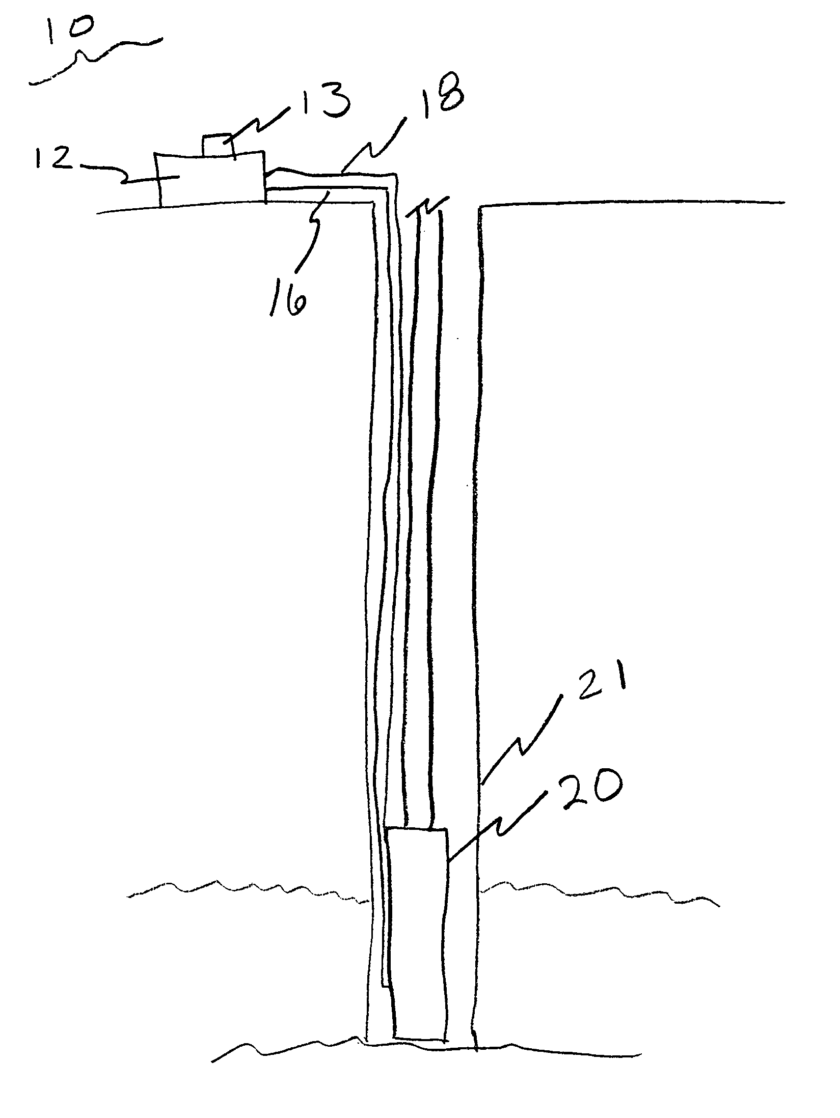
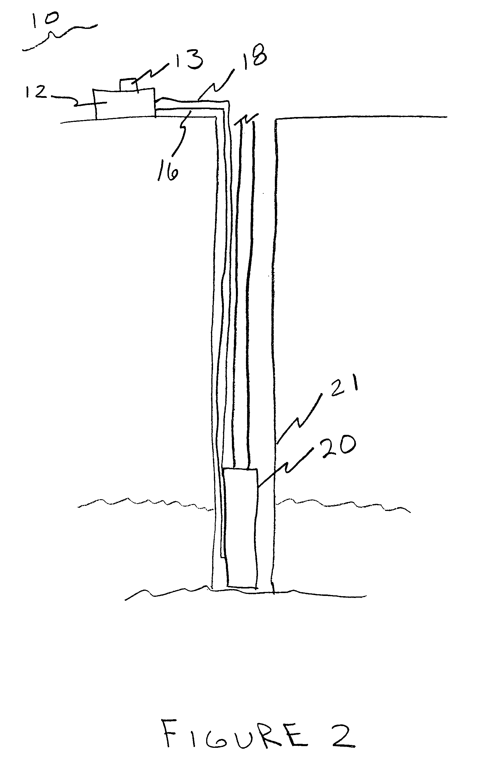
[0055] With reference to FIG. 2, the improved hydraulic down-hole oil recovery system of the present invention is identified generally by the reference number 10. In the preferred embodiment, device 10 includes surface pump unit 12. Surface pump unit 12 sends a power fluid 14 through upstroke power line 16 during one cycle and sends power fluid 14 through down-stroke power line 18 in a following down-stroke cycle. Surface unit 12 reversibly engages with power lines 16 and 18 so as to form a fluid-tight seal, such seal is formed by standard tube fittings as known in the art. In the preferred embodiment, pump unit 12 is a pressure pump, modified to contain a“switch off pressure sensor”13 which reads the pressure at the surface pump on both the upstroke and the down-stroke. At the point each stroke is carried out, pressure increases beyond a preset “switch off” point where sensor 13 sends a signal to pump 12 to begin the next stroke. Further, surface unit 12 transfers power fluid 14 by...


PUM


Abstract

An improved hydraulic downhole oil recovery system that incorporates an above ground unit and a submersible, reciprocating downhole pump unit. This system, by pumping oil to the surface both during the upstroke and down-stroke, is able to continuously pump oil to the surface as not previously possible. Oil production is doubled with virtually no increase in energy consumption during operation. Water-based fluid, rather than hydraulic fluid, is responsible for actuating the reciprocating downhole pump unit. The water-based fluid is transferred through the system using coil tubing. The system further relies upon coil exterior production tubing to provide exceptional advantage in deviated oil wells.

Description

CITATION TO PARENT APPLICATION(S) [0001] This is a continuation-in-part with respect to U.S. patent application Ser. No. 10 / 945,962, filed on Sep. 20, 2004, from which priority is claimed pursuant to 35 U.S.C. 120; which is a continuation-in-part with respect to U.S. patent application Ser. No. 10 / 945,530, filed on Sep. 20, 2004, from which priority is claimed pursuant to 35 U.S.C. 120; which is a continuation-in-part with respect to U.S. patent application Ser. No. 10 / 884,376, filed on Jul. 2, 2004, from which priority is claimed pursuant to 35 U.S.C. 120.BACKGROUND OF THE INVENTION [0002] 1. Field of the Invention [0003] Applicant's invention generally relates to an improved hydraulic downhole oil recovery system. More specifically, applicant's invention relates to an oil recovery system that employs coil tubing, in both its production tubing and fluid transfer tubing, and water-based fluid, rather than hydraulic fluid, to offer its user tremendous advantages in view of systems kn...

Claims


Application Information

Patent Timeline
Patent Type & Authority Applications(United States)
IPC IPC(8): E21B43/00
CPCE21B43/129F16H2007/0859F16H2007/0806F16H7/0836
Inventor CRAWFORD, JOE
Owner CRAWFORD JOE
Why Eureka
Try Eureka