Wing-In-Ground-Effect Craft

a technology of ground-effect craft and wings, which is applied in the field of aircraft, can solve the problems that the acceptance of wing-in-ground-effect technology is barely limited, and achieve the effect of easy ground-effect fligh

Inactive Publication Date: 2007-11-29
ELLNOR PIET
View PDF7 Cites 12 Cited by
  • Summary
  • Abstract
  • Description
  • Claims
  • Application Information

AI Technical Summary

Benefits of technology

[0047] Preferably said wing-in-ground-effect craft includes a further propulsion unit in the form of a water propulsion means extending below said hull, preferably in the form of a retractable leg. The retractable leg could inclu

Problems solved by technology

However, to date, wing-in-ground-effect technology has gained barely limi

Method used


Image

  • Wing-In-Ground-Effect Craft
  • Wing-In-Ground-Effect Craft
  • Wing-In-Ground-Effect Craft

Examples


first embodiment

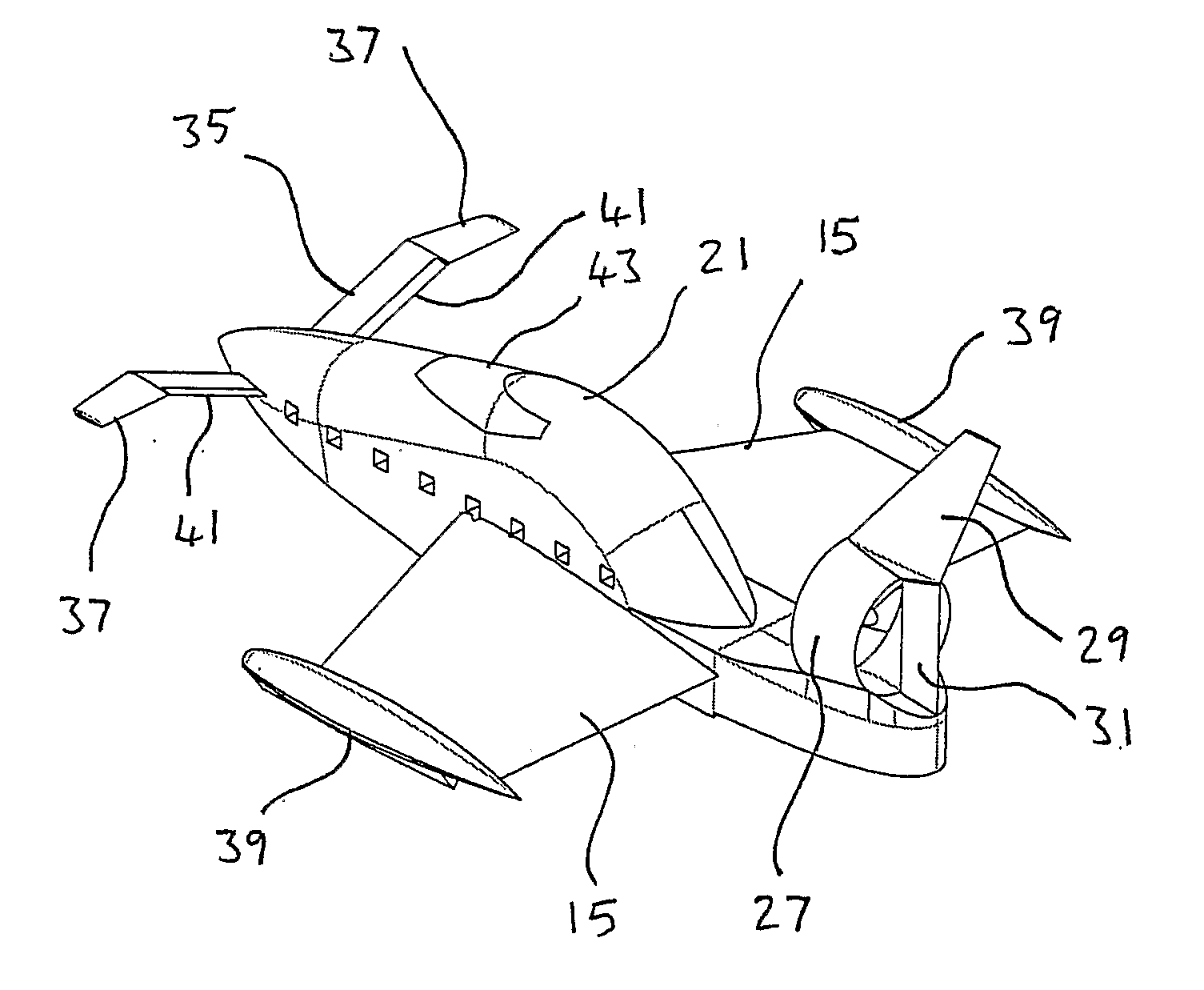
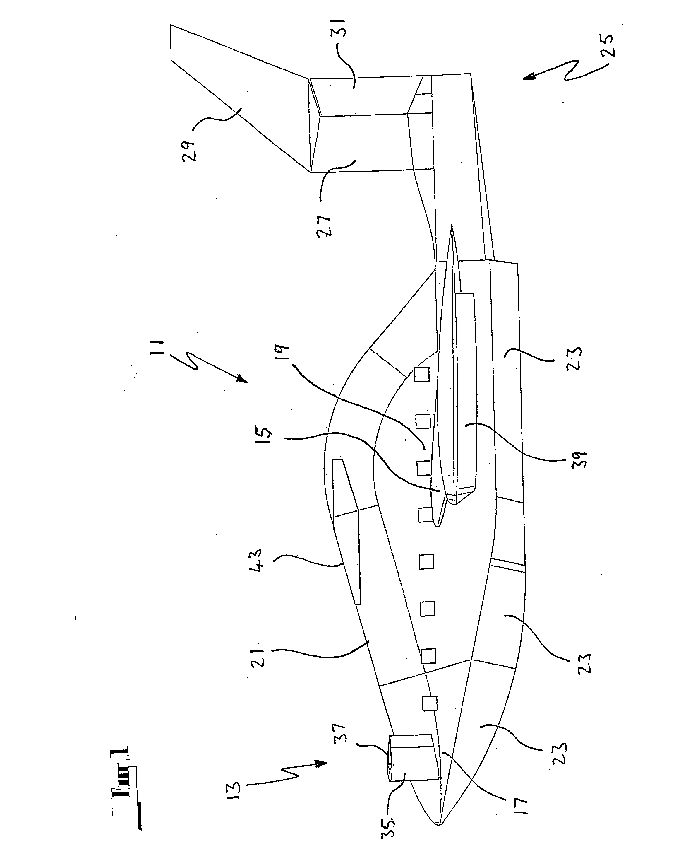
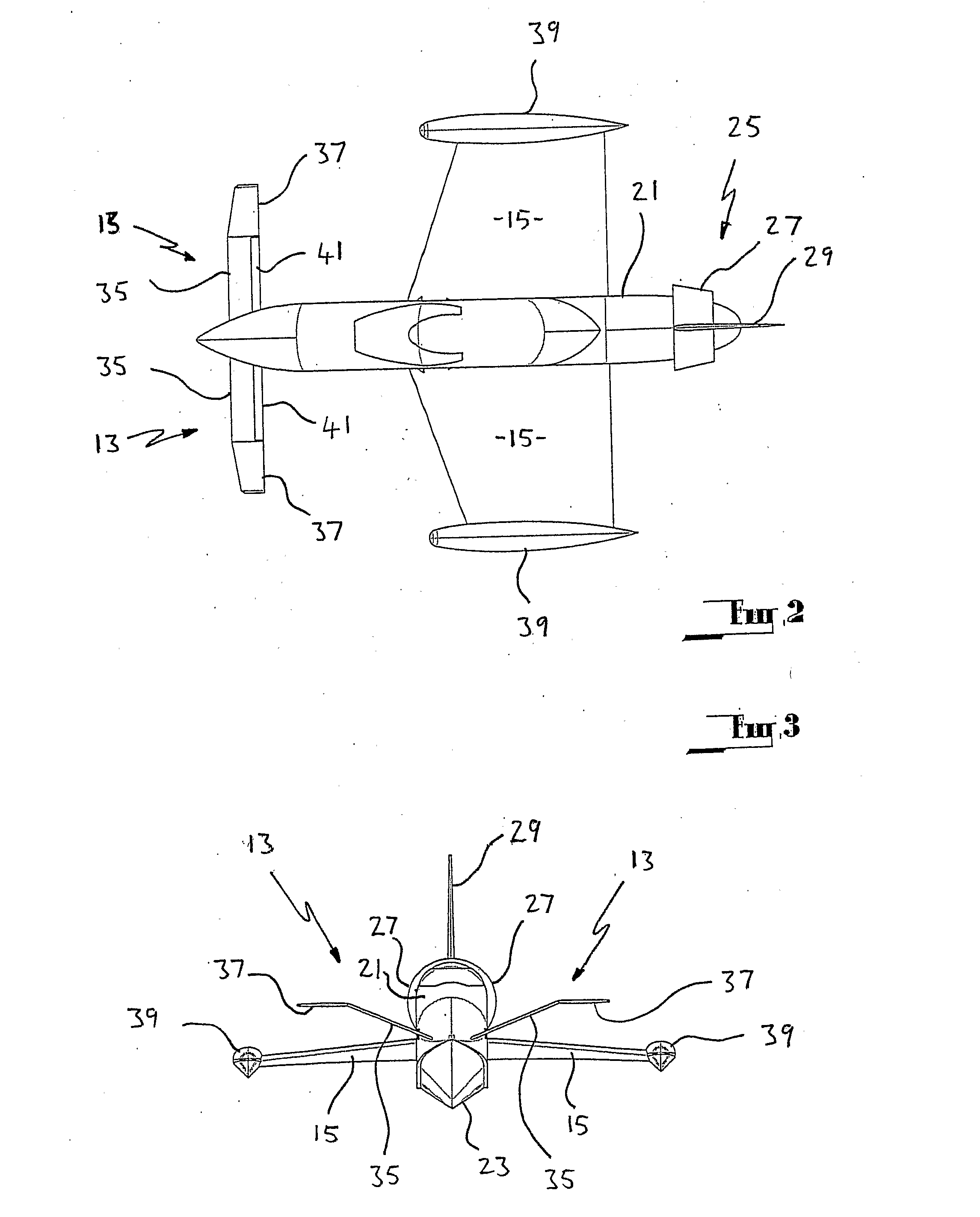
[0057] Both embodiments are an amphibious wing-in-ground-effect craft 11. The wing-in-ground-effect craft 11 is characterised by canard configuration, having a loaded canard forewing 13 and a main wing 15 of forward delta configuration attached to fore 17 and mid 19 sections of a body 21 respectively. The body 21 is formed with an integral planing hull 23, and extends rearward to a tail section 25 which incorporates a ducted fan 27, and a vertical stabiliser 29. A rudder 31 is located in the exhaust of the ducted fan 27, for steering the craft 11. The ducted fan 27 has a three bladed impellor 33, which in the first embodiment is belt driven from a turbocharged 1800 cc Subaru EA82 liquid cooled internal combustion engine. With the rudder 31 mounted in the full flow of the duct 27, it is configured to serve as a stator, acting to reduce the induced spiral in the airflow exiting the duct 27. While these embodiments have a five bladed fan, it will be appreciated that the number of blade...

second embodiment

[0073] Wing-in-ground-effect craft are significantly inefficient at take-off due to “hump” drag and require almost 200% of cruise power to overcome this drag. the wing-in-ground-effect craft overcomes this requirement to a large degree by incorporating the second drive units either driving a conventional propeller through a retractable leg, a surface effect propeller or a Hamilton jet drive. Once clear of the sea surface the wet drive unit is shut down and in the case of the leg or SE propeller the leg is rotated or the SE prop feathered. The wet drive also provides a high degree of low speed manoeuvrability that would not be achievable with the ducted fan. The dual system also provides a degree of redundancy in the event of mechanical failure providing the ability to manoeuvre and get the vessel up on the plane using either drive.

[0074] Dimensions of the second embodiment are as follows:

Length Over AllMeter16Width Over AllMeter10Height Over AllMeter7WeightDrykg2,750FuelLitre500Cr...


PUM


Abstract

An wing-in-ground-effect craft (11) having a loaded canard forewing (13) and a main forward delta configuration wing (15) attached to fore (17) and mid (19) sections of a body (21) respectively. The body (21) is formed with an integral planning hull (23) for amphibious applications, extending rearward to a tail section (25) which incorporates a ducted fan (27), and a vertical stabiliser (29). Rudder (31) is located in the exhaust of the ducted fan (27) for steering the craft (11), and serves as a stator to reduce spiral induced in the airflow exiting the duct (27). The canard forewing (13) has about 12% of the area of the main wing (15), and has inner portions (35) having a dihedral configuration disposed at a first angle of inclination from the vertical of 68° (equating to a dihedral angle of 22°), and outer portion (37) disposed at a first angle of inclination from the vertical of about 91° (equating to an anhedral angle of about 1°). The inner portions (35) have an angle of attack of 7.5%, while the outer portions (37) have an angle of attack of 4.5°. The main wing (15) has a flat to slightly anhedral configuration and an angle of attack of from 4° to 4.5°. The main wing (15) incorporates a pontoon float (39) attached on the outer end of each main wing (15). The canard forewing (13) has control surfaces in the form of elevons (41) attached behind the inner portions (35).

Description

FIELD OF THE INVENTION [0001] This invention relates to aircraft and in particular to wing-in-ground-effect craft, although not limited to ground effect craft. Particularly, this invention relates to water borne wing-in-ground-effect craft. BACKGROUND ART [0002] Maritime logistic and supply support relies on the use of marine (water borne) vessels, helicopters and in some cases light aircraft for transportation of materials and personnel to and from offshore facilities and locations. [0003] Typically bulk and heavy material is transported using supply boats, self propelled barges and the like, personnel may be carried on fast crew boats, ferries, helicopters or light aircraft dependent on the facility location, availability of a suitable airstrip and distance from the point of embarkation. [0004] Research suggests that a niche exists in the maritime personnel and light materials transportation environment for distances between 50 and 1,000 miles. Below 50 miles fast surface vessels ...

Claims


Application Information

Patent Timeline
IPC IPC(8): B64C5/04B60V1/08B64C39/12
CPCB60V1/08Y02T70/12B64C39/12B63B1/322Y02T70/10
Inventor ELLNOR, PIET
Owner ELLNOR PIET
Why Eureka
Try Eureka