Color adjusting apparatus and method for light source

a technology of color adjusting apparatus and light source, which is applied in the direction of colour separation/tonal correction, instruments, transportation and packaging, etc., can solve the frequency response of mutual interference between color signals, and achieve the effect of improving the output intensities of any specific colors, and improving the performance of light sources

Active Publication Date: 2007-11-29
INTELLECTUAL VENTURES I LLC
View PDF34 Cites 3 Cited by
  • Summary
  • Abstract
  • Description
  • Claims
  • Application Information

AI Technical Summary

Benefits of technology

[0011] The present invention provides a color adjusting apparatus and method. A reflector with a required color is added to a light source of a scan module. A plating film with the required color is formed on a lens. Or alternatively, the light source is directly switched to the required color. Thus, the inconsistent output intensities for the three primary colors, red, green and blue light, of the charge-coupled device caused by different brightness of the light source, different wavelength transmission of the lens and the different light sensitivities of the charge-coupled device is improved.

Problems solved by technology

This is very costly and time consuming.
Therefore, frequency response of mutual interference between color signals occurs.

Method used


Image

  • Color adjusting apparatus and method for light source
  • Color adjusting apparatus and method for light source
  • Color adjusting apparatus and method for light source

Examples


first embodiment

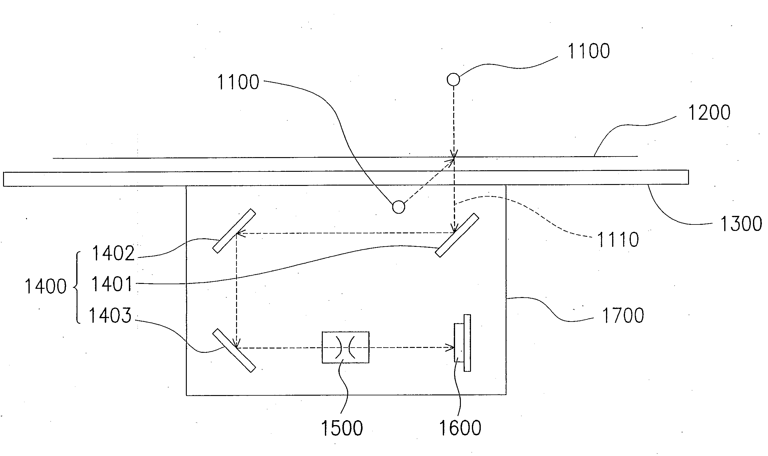
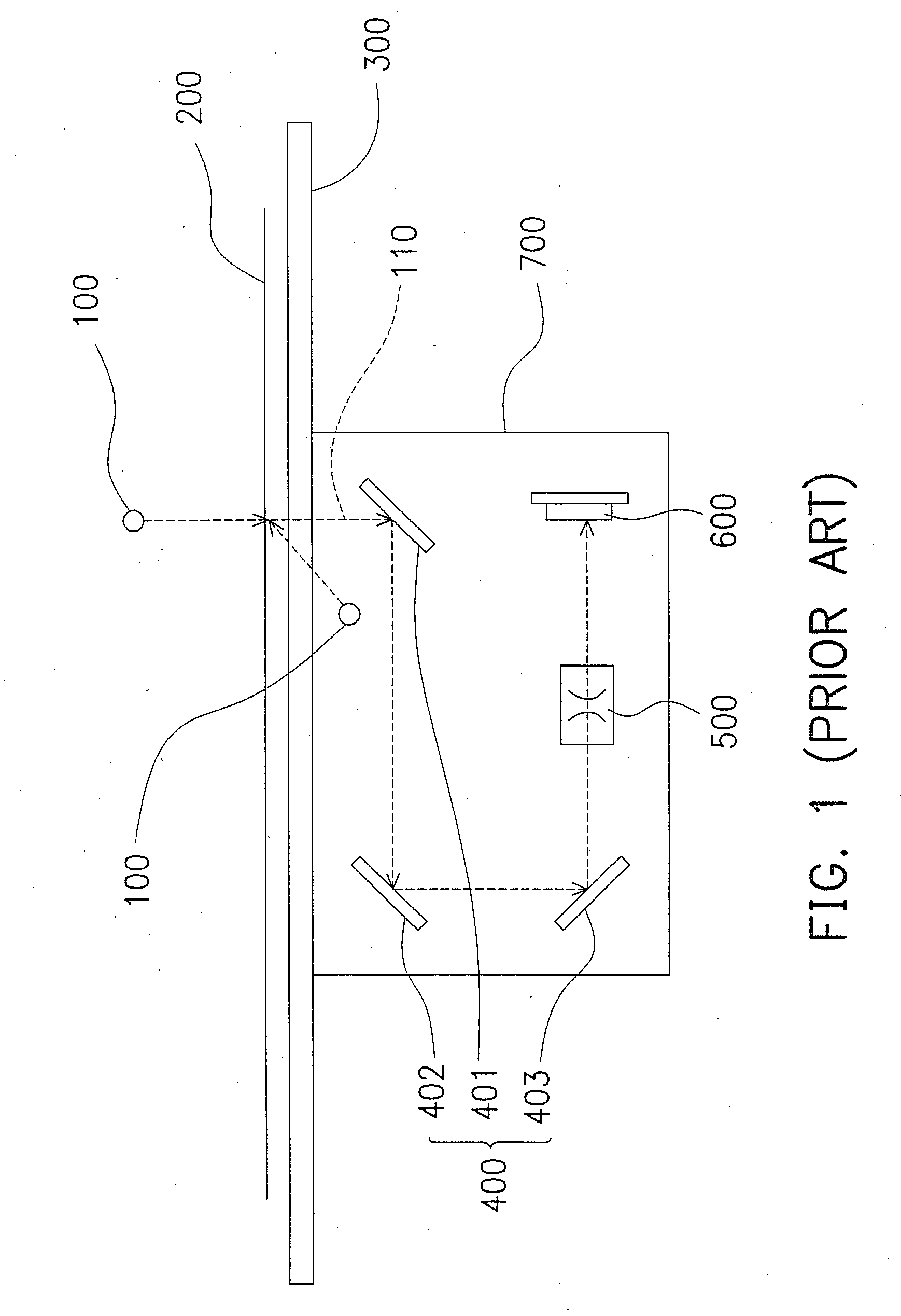
[0034]FIG. 3 shows a cross-sectional view of an optical scan module according to the present invention. The optical scan module 1700 comprises a light source 1100, a reflection mirror set 1400, a lens set 1500 and an optical detector, for example, a charge-coupled device (CCD) 1600. While performing scan, the light source 1100 radiates a document disposed on a transparent board 1300. By reflection (where the light source 1100 is located under the transparent board 1300) or projection (where the light source 1100 is located over the transparent board 1300), an imaging light 1110 is obtained. The reflection mirror set 1400 is assembled by reflection mirrors 1401, 1402 and 1403 located on an optical path of the imaging light 1110, such that the imaging light 1110 is directed to the reflection mirror set 1400. The imaging light 1110 is then reflected from the reflection mirror set 1400 and transmitted to the lens set 1500. The lens set 1500 receives and displays the imaging light 1116 o...

second embodiment

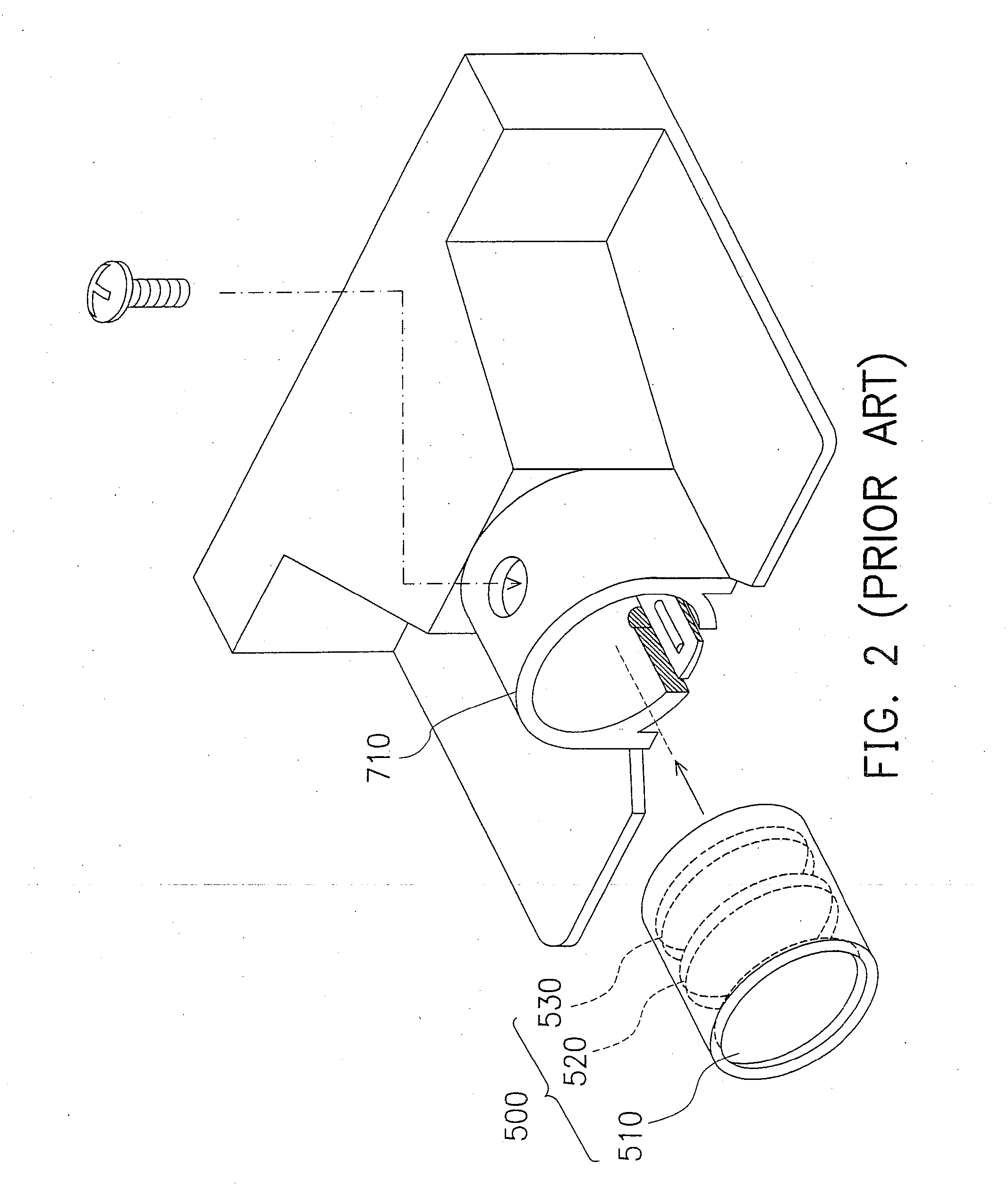
[0038] Referring to FIG. 5, a side view of a lens set of an optical scan module in a second embodiment of the present invention is shown. Similarly, the lens set 1500 includes a single lens format assembled by multiple lenses (1510, 1520 and 1530 in this embodiment). To improve the inconsistent intensities for red, green and blue lights, a surface 1512 of the lens 1510 is coated with a transparent plating film 1540 with a specific color. The method for forming the transparent plating film 1540 includes evaporation plating.

[0039] For example, when it is found that the charge-coupled device 1600 has insufficient intensity for red light, a red transparent plating film 1540 is formed to enhance the red light output performance of the light source. When the green light intensity output from the charge-coupled device 1600 is insufficient, a green transparent plating film 1540 is formed. When the blue light intensity of the charge-coupled device 1600 is insufficient, a blue transparent pl...


PUM

PropertyMeasurementUnit
coloraaaaaaaaaa
colorsaaaaaaaaaa
transparentaaaaaaaaaa

Abstract

Color adjusting apparatus and method for a light source. A reflector of a required color is added to a light source of a scan module, a plating film of the required color is formed on a lens, or the lens is dyed with the required color. Or alternatively, the color of the light source is directly changed into the required color. As a result, the inconsistent intensities for the light in the primary color, red, green and blue output from the charge-coupled device caused by different brightness of the light source, different wavelength transmission of the lens, and different light sensitivity of the charge-coupled device is improved.

Description

CROSS REFERENCE TO RELATED APPLICATIONS [0001] This application claims the priority benefit of Taiwan application serial no. 91105037, filed on Mar. 18, 2002. BACKGROUND OF INVENTION [0002] 1. Field of the Invention [0003] The invention relates in general to a color adjusting apparatus and method for a light source. More particularly, the invention relates a color adjusting apparatus and method of use for a light source of an optical scan module. [0004] 2. Related Art of the Invention [0005] As image input, operation and processing have caused popular interest, the scanner becomes a basic accessory for many computer users. Through the scanner, text or graphs in documents, magazines, books or pictures can be scanned and input into a computer for further processing. The platform scanner is the most common type among various kinds of scanners. In the platform scanner, the scan module, installed under a transparent platform, can be pulled back and forth to scan the document on the trans...

Claims


Application Information

Patent Timeline
Patent Type & Authority Applications(United States)
IPC IPC(8): H04N1/46G03F3/08H04N1/028H04N1/48
CPCH04N1/02815H04N1/48H04N1/0287H04N1/0285
Inventor CHEN, PI-CHEN
Owner INTELLECTUAL VENTURES I LLC
Why Eureka
Try Eureka